Building a prototype
This section will focus on the practical aspects of our engineering project by briefly describing how we built a functioning prototype. The control circuit was built around a microcontroller board, the circuit below includes an Arduino Uno R3 board, but the system could be adapted analogously using any other microcontroller. The main advantage of this setup is that it allows for quick changes without the need to swap components and flexibility is a key factor when prototyping. The list of electrical components we used is as follows:
| # | Component | Model/Properties |
|---|---|---|
| 1 | 4 x AA Battery: Standard 4 x AA battery 6.0 V | Battery Connector 4 x AA |
| 4 | Pushbutton: Momentary switches that close a circuit when pressed. | |
| 2 | Potentiometer: A variable resistor. When the external sides of the potentiometer are connected to voltage and ground, the middle leg will give the difference in voltage as you turn the knob. Also know as pot. | 10 kOhms |
| 1 | Slideswitch: A switch that allows you to close or open a circuit permanently. | |
| 2 | Servo: Type of geared motor that can only rotate 180 degrees. It's controlled by electronic pulses that tell the motor to which position it should move. | MG996R - High Torque - Metal Gear |
| 2 | 3-Pin Temperature Sensor [DS18B20] | DS18B20 - Temp. range [-55°C/+125°C] |
| 1 | LCD 16 x 2: A very common display that comes in the Arduino kit and works with "LiquidCrystal" library. | |
| 4 | Pull-down Resistor: Resist the flow of electrical energy in a circuit, changing the voltage and current as a result. | 10 kOhms - R2/3/4/5 |
| 1 | Resistor: Resist the flow of electrical energy in a circuit, changing the voltage and current as a result. | 4.7 kOhms - R6 |
| 1 | Arduino Uno R3: The official Arduino Uno Rev3 |
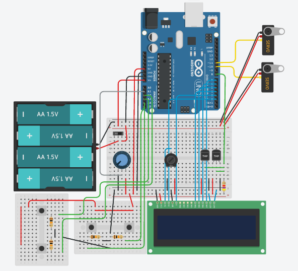
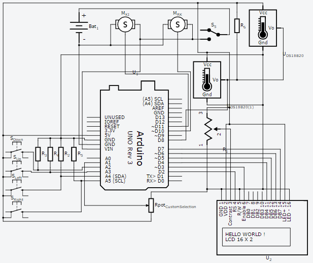
The wiring of the circuit is illustrated below, notice the schematics and the wiring diagram. The order of the pins on the microcontroller board is not necessarily important, but any changes need to be reflected in the code. Furthermore, components like servomotors can only be controlled with Pulse Width Modulation (PWM), so the pins used on the Arduino (10 and 11 in our case) need to support it. Although we decided to include an LCD screen and four pushbuttons for navigation in our design, the same result could be achieved with a shield or by leaving the screen out completely in order to simplify the design and reduce power consumption.
The central pin of the two temperature sensors (marked TMP in the circuit above) are connected on a single bus to the Arduino. The bus itself needs to be connected to the +5V supply with a 4.7 kOhms pull-up resistor, as specified in the manufacturer datasheet. Each one of the sensors will be uniquely identified by a digital index, but there is no easy way to work it out unless the circuit is tested beforehand. Additionally, note that, by using the LiquidCrystal library, four terminals of the LCD screen become unnecessary. To conclude, the circuit above includes two 10 kOhm potentiometers, the black one is used to regulate the contrast of the LCD screen and the blue one can be used for menu navigation in conjunction with the four pushbuttons.
The Arduino code can be found below. Some of the parameters will need adjustments depending on the setup of the system. Since we are only using potential gravitational energy to drive the flow, the relative heights of the three main components (reservoir, solar kettle and incubator) will affect the volume flow rate within the pipes. Three programs have been implemented, one for yogurt production, one for pasteurization of milk and a third custom one. The custom program is extremely versatile and allows the user to run a cycle at a specific temperature (within a reasonable range) for a set period of time. The two valves can also be opened and closed arbitrarily.
We used five additional libraries and the most notable ones are DallasTemperature.h, which makes the communication with the temperature sensors extremely easy and MenuBackEnd.h, which provides an easy way to setup a menu structure for the LCD screen. The use of servomotors to control ball valves allowed us a much finer control of the water flow so we exploited this characteristic in the code by implementing incremental motion of the valve mechanisms. Note that, although the temperature sensors [DS18B20] output values with two decimal places, all measurements are affected by an absolute error of ±0.5°C. As a consequence, the readings are digitally truncated to integers.
/*
  Solar Water Bath Incubator Project
  ***
  The following code controls the state of 2 servo motor actuated valves
  in order to regulate the temperature inside a water bath incubator.
  ____________________________________________________________________

  Copyright Simone Marcigaglia
  Contact: glasgow.igem.2016@gmail.com
  Created on 29/06/2016
  iGem 2016 Glasgow
  ____________________________________________________________________

  This program is free software: you can redistribute it and/or modify
  it under the terms of the GNU General Public License as published by
  the Free Software Foundation, either version 3 of the License, or
  (at your option) any later version.
  ____________________________________________________________________

  This program is distributed in the hope that it will be useful,
  but WITHOUT ANY WARRANTY; without even the implied warranty of
  MERCHANTABILITY or FITNESS FOR A PARTICULAR PURPOSE.  See the
  GNU General Public License for more details.
*/

#include <Servo.h>
#include <DallasTemperature.h>
#include <OneWire.h>
#include <LiquidCrystal.h>
#include <MenuBackend.h>

// Temperature data wire is pin 8 on the Arduino
#define ONE_WIRE_BUS 8

//SERVOMOTOR VARIABLES_____________________________________________
Servo valveKI;           //Servomotor controlling the Kettle-Incubator valve
Servo valveRK;           //Servomotor controlling the Reservoir-Kettle valve
int pos = 0;             //position of the servomotor
int closedValve = 0;     //angle corresponding to the closed valve
int openValve = 90;      //angle corresponding to the open valve

//TEMP SENSORS VARIABLES___________________________________________
// Setup a oneWire instance to communicate with any OneWire devices
// (not just Maxim/Dallas temperature ICs)
OneWire oneWire(ONE_WIRE_BUS);
// Pass our oneWire reference to Dallas Temperature.
DallasTemperature thermo(&oneWire);
int Tref = 0;         //target temperature
const uint8_t Ty = 1; //index of the temp sensor inside the incubator
const uint8_t Tw = 0; //index of the temp sensor inside solar kettle

//LCD NAVIGATION VARIABLES_________________________________________
int lastButtonPushed = 0;
boolean lastButtonUpState = LOW;     // the previous reading from the Up input pin
boolean lastButtonDownState = LOW;   // the previous reading from the Down input pin
boolean lastButtonLeftState = LOW;   // the previous reading from the Left input pin
boolean lastButtonRightState = LOW;  // the previous reading from the Right input pin

long lastUpDebounceTime = 0;     // the last time the output pin was toggled
long lastDownDebounceTime = 0;   // the last time the output pin was toggled
long lastLeftDebounceTime = 0;   // the last time the output pin was toggled
long lastRightDebounceTime = 0;  // the last time the output pin was toggled
long debounceDelay = 125;        // the debounce time

//LiquidCrystal lcd(rs, e, d4, d5, d6, d7);
LiquidCrystal lcd(2, 3, 4, 5, 6, 7);

//Menu items declaration
MenuBackend menu = MenuBackend(menuUsed, menuChanged);
MenuItem CycleItem1 = MenuItem("Yogurt");
MenuItem StartYogurt = MenuItem("StartYogurt");
MenuItem CycleItem2 = MenuItem("Pasteur");
MenuItem StartPasteur = MenuItem("StartPasteur");
MenuItem CycleItem3 = MenuItem("Custom");
MenuItem SelectTemp = MenuItem("SelectTemp");
MenuItem SelectHours = MenuItem("SelectHours");
MenuItem SelectMinutes = MenuItem("SelectMinutes");
MenuItem SelectSeconds = MenuItem("SelectSeconds");
MenuItem StartCustom = MenuItem("StartCustom");
MenuItem CycleItem4 = MenuItem("OperateValves");
MenuItem SwitchStateRK = MenuItem("SwitchStateRK");
MenuItem SwitchStateKI = MenuItem("SwitchStateKI");

//PIN ALLOCATION___________________________________________________
const uint8_t Up = A3;     //Pin UP button
const uint8_t Down = A2;   //Pin DOWN button
const uint8_t Right = A5;  //Pin RIGHT button
const uint8_t Left = A4;   //Pin LEFT button
const uint8_t Knob = A1;   //Pin Potentiometer

//CUSTOM PROGRAM VARIABLES_________________________________________
boolean isTemp = false;
boolean isHours = false;
boolean isMinutes = false;
boolean isSeconds = false;
int hours = 0;
int minutes = 0;
int seconds = 0;

//FLOW CONTROL VARIABLES____________________________________________
int Vkettle = 0;
int Vmax = 1000;        //Maximum volume inside the kettle [mL]
float VdotMax = 30;     //Maximum volume flow rate [mL/s] with the valve fully open
            //this value can be easily found experimentally and varies
            //depending upon system properties
float Vdot = 0;         //Current volume flow rate [mL/s]

void setup() {

  //INPUT pins (buttons)
  pinMode(Up, INPUT);
  pinMode(Down, INPUT);
  pinMode(Left, INPUT);
  pinMode(Right, INPUT);
  pinMode(Knob, INPUT);

  //Start up the servo motor actuated valves
  //valveKI--> valve connecting kettle to incubator
  //valveRK--> valve connecing reservoir to kettle
  valveKI.attach(11);
  valveKI.write(closedValve);
  valveRK.attach(10);
  valveRK.write(closedValve);

  // Start up the temperature sensors library
  thermo.begin();

  //Start up the LCD
  lcd.begin(16, 2); //16x2 LCD screen

  //Configure the menu structure
  menu.getRoot().addRight(CycleItem4);
  menu.getRoot().addRight(CycleItem3);
  menu.getRoot().addRight(CycleItem2);
  menu.getRoot().addRight(CycleItem1);
  CycleItem1.addAfter(CycleItem2).addAfter(CycleItem3).addAfter(CycleItem4);
  CycleItem1.addRight(StartYogurt);
  CycleItem2.addRight(StartPasteur);
  CycleItem3.addRight(SelectTemp).addRight(SelectHours).addRight(SelectMinutes).addRight(SelectSeconds).addRight(StartCustom);
  CycleItem4.addRight(SwitchStateRK).addAfter(SwitchStateKI);
  menu.toRoot();
}

void loop() {
  //menu navigation procedures
  readButtons();
  navigateMenus();
  //A potentiometer is used to set the parameters needed to run the custom
  //program, the boolean variables are used to check what menu item is currently
  //being used and the value is then stored iin the respective variable
  if (isTemp) {
  int MaxTemp = 85;
  int MinTemp = 25;
  Tref = map(analogRead(Knob), 0, 1023, MinTemp, MaxTemp);
  lcd.setCursor(7, 1);
  lcd.print(Tref);
  }
  if (isHours) {
  hours = map(analogRead(Knob), 0, 1023, 0, 24); //Max cycle length = 24 h
  lcd.setCursor(7, 1);
  lcd.print(hours);
  }
  if (isMinutes) {
  minutes = map(analogRead(Knob), 0, 1023, 0, 59);
  if (minutes < 10) {
    lcd.setCursor(7, 1);
    lcd.print(0);
    lcd.print(minutes);
  } else {
    lcd.setCursor(7, 1);
    lcd.print(minutes);
  }
  }
  if (isSeconds) {
  seconds = map(analogRead(Knob), 0, 1023, 0, 59);
  if (seconds < 10) {
    lcd.setCursor(7, 1);
    lcd.print(0);
    lcd.print(seconds);
  } else {
    lcd.setCursor(7, 1);
    lcd.print(seconds);
  }
  }
}

//MENU NAVIGATION_________________________________________________
void menuChanged(MenuChangeEvent changed) {

  MenuItem newMenuItem = changed.to; //get the destination menu

  lcd.clear(); //set the start position for lcd printing to the first row
  isTemp = false;
  isHours = false;
  isMinutes = false;
  isSeconds = false;

  //Assign each mennu item to specific lcd behaviour
  if (newMenuItem.getName() == menu.getRoot()) {
  lcd.print("Tinc   TH2O     ");
  lcd.setCursor(0, 1);
  lcd.print(readTemp(Ty));
  lcd.setCursor(7, 1);
  lcd.print(readTemp(Tw));
  lcd.setCursor(13, 1);
  } else if (newMenuItem.getName() == "Yogurt") {
  lcd.print("Make yogurt     ");
  lcd.setCursor(0, 1);
  lcd.print("<--          -->");
  } else if (newMenuItem.getName() == "StartYogurt") {
  lcd.print("Back       Start");
  lcd.setCursor(0, 1);
  lcd.print("<--          -->");
  } else if (newMenuItem.getName() == "Pasteur") {
  lcd.print("Pasteurise[HTST]");
  lcd.setCursor(0, 1);
  lcd.print("<--          -->");
  } else if (newMenuItem.getName() == "StartPasteur") {
  lcd.print("Back       Start");
  lcd.setCursor(0, 1);
  lcd.print("<--          -->");
  } else if (newMenuItem.getName() == "Custom") {
  lcd.print("Custom program  ");
  lcd.setCursor(0, 1);
  lcd.print("<--          -->");
  } else if (newMenuItem.getName() == "SelectTemp") {
  lcd.print("Set temperature ");
  lcd.setCursor(0, 1);
  lcd.print("<--          -->");
  isTemp = true;
  } else if (newMenuItem.getName() == "SelectHours") {
  lcd.print("Set Hours       ");
  lcd.setCursor(0, 1);
  lcd.print("<--          -->");
  isHours = true;
  } else if (newMenuItem.getName() == "SelectMinutes") {
  lcd.print("Set minutes     ");
  lcd.setCursor(0, 1);
  lcd.print("<--          -->");
  isMinutes = true;
  } else if (newMenuItem.getName() == "SelectSeconds") {
  lcd.print("Set seconds     ");
  lcd.setCursor(0, 1);
  lcd.print("<--          -->");
  isSeconds = true;
  } else if (newMenuItem.getName() == "StartCustom") {
  lcd.print("Back       Start");
  lcd.setCursor(0, 1);
  lcd.print("<--          -->");
  } else if (newMenuItem.getName() == "OperateValves") {
  lcd.print("Operate valves  ");
  lcd.setCursor(0, 1);
  lcd.print("<--          -->");
  } else if (newMenuItem.getName() == "SwitchStateKI") {
  if (valveKI.read() == 0) {
    lcd.print("Open KI Valve?  ");
    lcd.setCursor(0, 1);
    lcd.print("<--          -->");
  } else {
    lcd.print("Close KI valve? ");
    lcd.setCursor(0, 1);
    lcd.print("<--          -->");
  }
  } else if (newMenuItem.getName() == "SwitchStateRK") {
  if (valveRK.read() == 0) {
    lcd.print("Open RK Valve?  ");
    lcd.setCursor(0, 1);
    lcd.print("<--          -->");
  } else {
    lcd.print("Close RK valve? ");
    lcd.setCursor(0, 1);
    lcd.print("<--          -->");
  }
  }
}

//Assigns specific functions to a menu being triggered
void menuUsed(MenuUseEvent used) {

  if (used.item.getName() == "StartYogurt") {
  Yogurt();
  } else if (used.item.getName() == "StartPasteur") {
  Pasteurise();
  } else if (used.item.getName() == "StartCustom")  {
  Custom();
  } else if (used.item.getName() == "SwitchStateKI")  {
  if (valveKI.read() == closedValve) {
    valveKI.write(openValve);
  } else {
    valveKI.write(closedValve);
  }
  } else if (used.item.getName() == "SwitchStateRK")  {
  if (valveRK.read() == closedValve) {
    valveRK.write(openValve);
  } else {
    valveRK.write(closedValve);
  }
  }
  menu.toRoot();  //back to Main
}

void  readButtons() { //read buttons status
  int reading;
  boolean buttonUpState = LOW;           // the current reading from the Up input pin
  boolean buttonDownState = LOW;         // the current reading from the Down input pin
  boolean buttonLeftState = LOW;         // the current reading from the Left input pin
  boolean buttonRightState = LOW;        // the current reading from the Right input pin

  //UP button___________________________________________________________
  // read the state of the switch into a local variable:
  reading = digitalRead(Up);

  // check to see if you just pressed the up button
  // (i.e. the input went from LOW to HIGH),  and you've waited
  // long enough since the last press to ignore any noise:

  // If the switch changed, due to noise or pressing:
  if (reading != lastButtonUpState) {
  // reset the debouncing timer
  lastUpDebounceTime = millis();
  }

  if ((millis() - lastUpDebounceTime) > debounceDelay) {
  // whatever the reading is at, it's been there for longer
  // than the debounce delay, so take it as the actual current state:
  buttonUpState = reading;
  lastUpDebounceTime = millis();
  }

  // save the reading.  Next time through the loop,
  // it'll be the lastButtonState:
  lastButtonUpState = reading;

  //Repeat for all four buttons
  //DOWN button_______________________________________________________
  reading = digitalRead(Down);
  if (reading != lastButtonDownState) {
  lastDownDebounceTime = millis();
  }
  if ((millis() - lastDownDebounceTime) > debounceDelay) {
  buttonDownState = reading;
  lastDownDebounceTime = millis();
  }
  lastButtonDownState = reading;

  //RIGHT button_______________________________________________________
  reading = digitalRead(Right);
  if (reading != lastButtonRightState) {
  lastRightDebounceTime = millis();
  }
  if ((millis() - lastRightDebounceTime) > debounceDelay) {
  buttonRightState = reading;
  lastRightDebounceTime = millis();
  }
  lastButtonRightState = reading;

  //LEFT button_______________________________________________________
  reading = digitalRead(Left);
  if (reading != lastButtonLeftState) {
  // reset the debouncing timer
  lastLeftDebounceTime = millis();
  }
  if ((millis() - lastLeftDebounceTime) > debounceDelay) {
  buttonLeftState = reading;
  lastLeftDebounceTime = millis();;
  }
  lastButtonLeftState = reading;

  if (buttonUpState == HIGH) {
  lastButtonPushed = Up;

  } else if (buttonDownState == HIGH) {
  lastButtonPushed = Down;

  } else if (buttonRightState == HIGH) {
  lastButtonPushed = Right;

  } else if (buttonLeftState == HIGH) {
  lastButtonPushed = Left;

  } else {
  lastButtonPushed = 0;
  }
}

void navigateMenus() {
  MenuItem currentMenu = menu.getCurrent();

  switch (lastButtonPushed) {
  case Right:
    if (!(currentMenu.moveRight())) { //pressing the RIGHT button with an item that has no items
    menu.use();                     //on its right will activate that specific menu item
    } else {
    menu.moveRight();
    }
    break;
  case Left:
    menu.moveLeft();
    break;
  case Down:
    menu.moveDown();
    break;
  case Up:
    menu.moveUp();
    break;
  }
  lastButtonPushed = 0; //reset the lastButtonPushed variable
}

//displays inner temperature and time left on lcd screen during cycle
void countdown(unsigned  long timeLeft) {
  unsigned long hoursLeft = (long) timeLeft / 3600;
  unsigned long minutesLeft = (long) (timeLeft - hoursLeft * 3600) / 60;
  unsigned long secondsLeft = (long) timeLeft - hoursLeft * 3600 - minutesLeft * 60;
  lcd.setCursor(0, 0);
  lcd.print("Tinc   Time left");
  lcd.setCursor(0, 1);
  lcd.print(readTemp(Ty));
  if (hoursLeft > 9) {
  lcd.setCursor(7, 1);
  lcd.print(hoursLeft);
  } else {
  lcd.setCursor(7, 1);
  lcd.print(0);
  lcd.setCursor(8, 1);
  lcd.print(hoursLeft);
  }
  lcd.setCursor(9, 1);
  lcd.print(":");
  if (minutesLeft > 9) {
  lcd.setCursor(10, 1);
  lcd.print(minutesLeft);
  } else {
  lcd.setCursor(10, 1);
  lcd.print(0);
  lcd.setCursor(11, 1);
  lcd.print(minutesLeft);
  }
  lcd.setCursor(12, 1);
  lcd.print(":");
  if (secondsLeft > 9) {
  lcd.setCursor(13, 1);
  lcd.print(secondsLeft);
  } else {
  lcd.setCursor(13, 1);
  lcd.print(0);
  lcd.setCursor(14, 1);
  lcd.print(secondsLeft);
  }
}

//TEMPERATURE CYCLER______________________________________________________

//Runs yogurt program (temperature at 43°C for 8 hours)
void Yogurt() {
  Tref = 43;
  hours = 8;
  minutes = 0;
  seconds = 0;
  ReachTemp(Tref);
  MantainTemp(Tref, hours, minutes, seconds);
  finish();
}

// Runs pasteurisation program (temperature at 72 °C for 15s - HTST standard)
void Pasteurise() {
  Tref = 72;
  hours = 0;
  minutes = 0;
  seconds = 15;
  ReachTemp(Tref);
  MantainTemp(Tref, hours, minutes, seconds);
  finish();
}

//Runs custom program (needs temperature and cycle duration)
void Custom() {
  ReachTemp(Tref);
  MantainTemp(Tref, hours, minutes, seconds);
  finish();
}

//Sends a temperature request on the sensor bus and reads the value from a specific
// temperature sensor (index)
float readTemp(int index) {
  // call sensors.requestTemperatures() to issue a global temperature
  // request to all devices on the bus
  thermo.requestTemperatures(); // Send the command to get temperatures
  float temp = 0;
  while (temp < 1) {                        //checks for sensible values
  temp = thermo.getTempCByIndex(index);   //sensor will occasionally output -127°C values
  //(if not working properly)
  }
  return temp;
}

//The function provides an easy way to stop a program
//returns false if the LEFT button was pressed for at least 2 s
boolean interrupt(int pin) {
  boolean current = digitalRead(pin);
  if (current == LOW) {
  return true;
  }  else {
  delay(1000);
  if (digitalRead(pin) == current) {
    delay(1000);
  }  if (digitalRead(pin) == current) {
    return false;
  }
  }
}

//Opens the valve to reach the desired temperature as quickly as possible
void ReachTemp(int Tref) {
  lcd.clear();
  lcd.setCursor(0, 0);
  lcd.print("Reaching temp...");
  lcd.setCursor(0, 1);
  lcd.print("T= ");
  lcd.setCursor(7, 1);
  lcd.print("*C");
  unsigned long start = 0;

  while (readTemp(Ty) < (Tref) && interrupt(Left)) {
  start = millis();
  lcd.setCursor(2, 1);
  lcd.print(readTemp(Ty));
  if (readTemp(Tw) < (readTemp(Ty) + 15)) { //checks if temperature of the water is high enough
    valveKI.write(closedValve);             //if it is, closes the valve until it raises
  } else {                                 //15 degrees above current temp.
    pos = FindAngle(Tref, readTemp(Ty));
    valveKI.write(pos);
    Vkettle = Vkettle + Vdot * ((millis() - start) / 1000);
    checkLevel();
  }
  delay(500);
  }
}

// Mantains the temperature in the incubator
// around Tref (in °C) for period (in ms)
void MantainTemp(int Tref, int h, int m, int s) {
  lcd.clear();
  //record time
  unsigned long zero = millis();          //initiate timer
  unsigned long secLeft = 0;
  unsigned long interval = 1000ULL * 60 * 60 * h + 1000ULL * 60 * m + 1000ULL * s;
  unsigned long start = 0;

  while (interval > (millis() - zero) && interrupt(Left)) {     //monitor time
  start = millis();
  secLeft = (interval + zero - millis()) / 1000;
  countdown(secLeft);

  if (readTemp(Tw) < Tref) {
    valveKI.write(closedValve);
  } else {
    pos = FindAngle(Tref, readTemp(Ty));
    valveKI.write(pos);
    Vkettle = Vkettle + Vdot * ((millis() - start) / 1000);
    checkLevel();
  }
  delay(500);
  }
  valveKI.write(0);
}

//Calculates to what extent the valve should be open depending on the current
//temperature difference in the incubator
int FindAngle(int Tref, int Tcurrent) {
  int angle = constrain((90 / (-0.1 * Tref + 9)) * (Tref - Tcurrent), 0, 90);
  //relationship between angle
  //and temperature difference
  Vdot = VdotMax / 90 * angle;
  return angle;
}
//this function is called at the end of a cycle and resets the system
void finish() {
  lcd.clear();
  lcd.setCursor(0, 0);
  lcd.print("DONE!!");
  delay(3000);
  menu.toRoot();
}

//Checks how much water is left in the solar kettle and
//lets water flow in from the reservoir when the level reaches a
//critical level
void checkLevel() {
  if (Vkettle > Vmax) {
  valveKI.write(closedValve);
  valveRK.write(openValve);
  delay(60000);
  valveRK.write(closedValve);
  Vkettle = 0;
  }
  Serial.println(Vkettle);
}
Regarding the physical components of the system, different combinations can be used in order to achieve the same result, but we will only present the parts we have used in order to build our prototype. As mentioned above, the system consists of three levels: a reservoir, a solar ‘kettle’ and a water bath incubator (in order of relative height with respect to a reference ground). Each one of these subsystems is connected to the next one in line with a length of silicone tubing. We used food-grade translucent silicone tubing (max operating temperature 260°C) with inner diameter di=8mm and outer diameter do=10mm. Our goal is to minimize thermal losses, so the thicker the wall the better its insulating properties will be.
A second design goal consists of increasing the flow rate through the system by positioning the reservoir as high above the solar kettle as possible (the same applies to the solar kettle with respect to the incubator). A higher flow rate will improve the performance of the system in terms of speed of response - the desired temperature will be reached faster and more steadily. The flow rate is also modulated by two inline valves, indicated in the Arduino code as valveRK (Reservoir-Kettle) and valveKI (Kettle-Incubator). We approached the design of these valves in two different ways, which are described in the section ‘Servo-Actuated valve’ below.
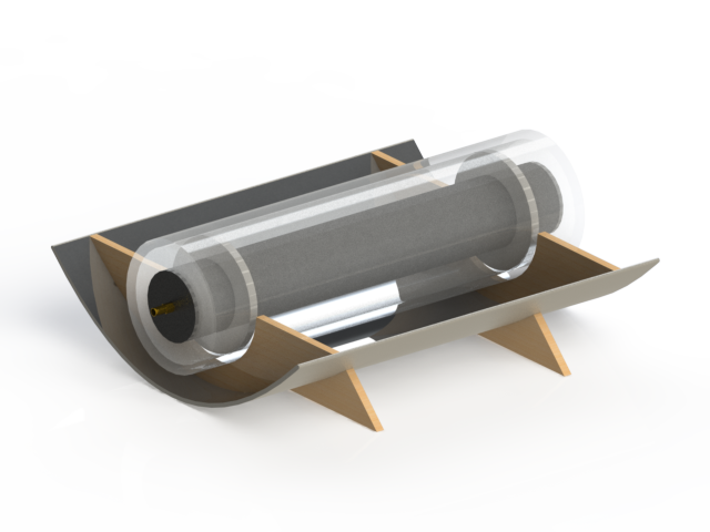
The system is also supposed to be accessible and easy to assemble, so, not considering the electrical components, we managed to build the remaining parts with scrap material found in the lab. The reservoir needs to be a water tight container that can house at least 5-10 L of ambient temperature water. The incubator could be similar, but best results are achieved if the container is also well insulated. Finally, the solar kettle is the trickiest component because of the high temperature that the water will reach inside it. The best option is to use a metallic cylinder (a large tin can could do the job), where two holes are drilled and serve as inlet and outlet. Ideally, this component will be painted black and it will be surrounded by a thin clear plastic layer in order to create a ‘greenhouse’ effect and maximise solar energy absorption (see example below).
A key idea behind this system is that the circulating water does not need to be clean. Any fluid with a sufficiently high boiling temperature will do the trick; we only decided to use water because of its vast availability. Additionally, the fluid could be recirculated in the system manually or by using a peristaltic pump.
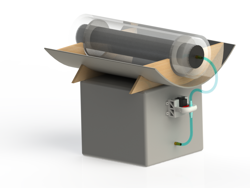
The CAD rendering above includes the solar kettle and the water bath incubator in one of our early designs. In this example, a cylindrical container is mounted on a parabolic reflector and aligned with its focal point. We also looked into various other designs (e.g. solar funnels), but, after we contacted an organization that has a lot more experience than us in this field, we realized that building our own solar concentrator might have been redundant. Therefore, we focused on the flexibility of our system and we tried to modify the design so that it could be used in existing solar reflectors.
Servo-actuated valve
The aim of this section is to describe how we connected our high-torque servomotors to functioning ball valves. A first attempt was successful despite the simplicity of the solution, we managed to join the servomotor head to a store-bought brass valve with epoxy glue, barbecue sticks and polystyrene. The use of a metallic part will guarantee a longer lifetime, but it will also be subject to frequent problems due to the stiffness of the valve. On the other hand, a custom-made 3d printed valve will be smoother to operate and can be personalised according to the required design specifications.
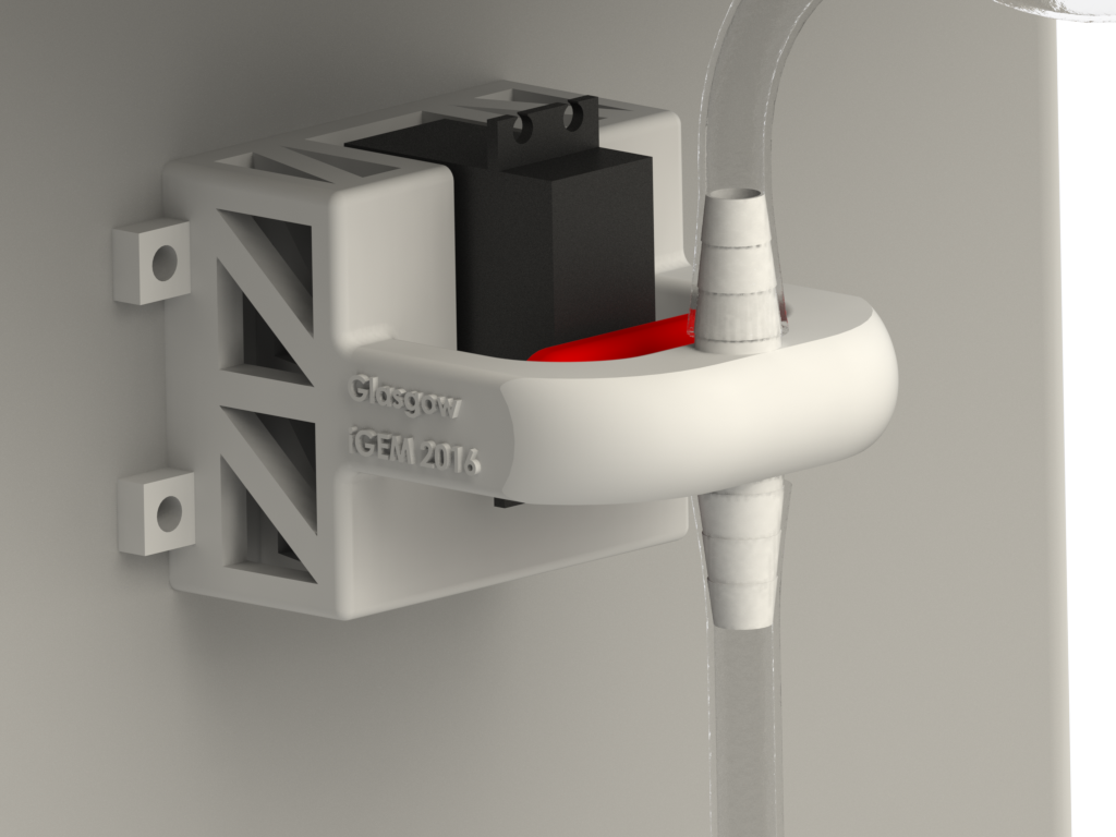
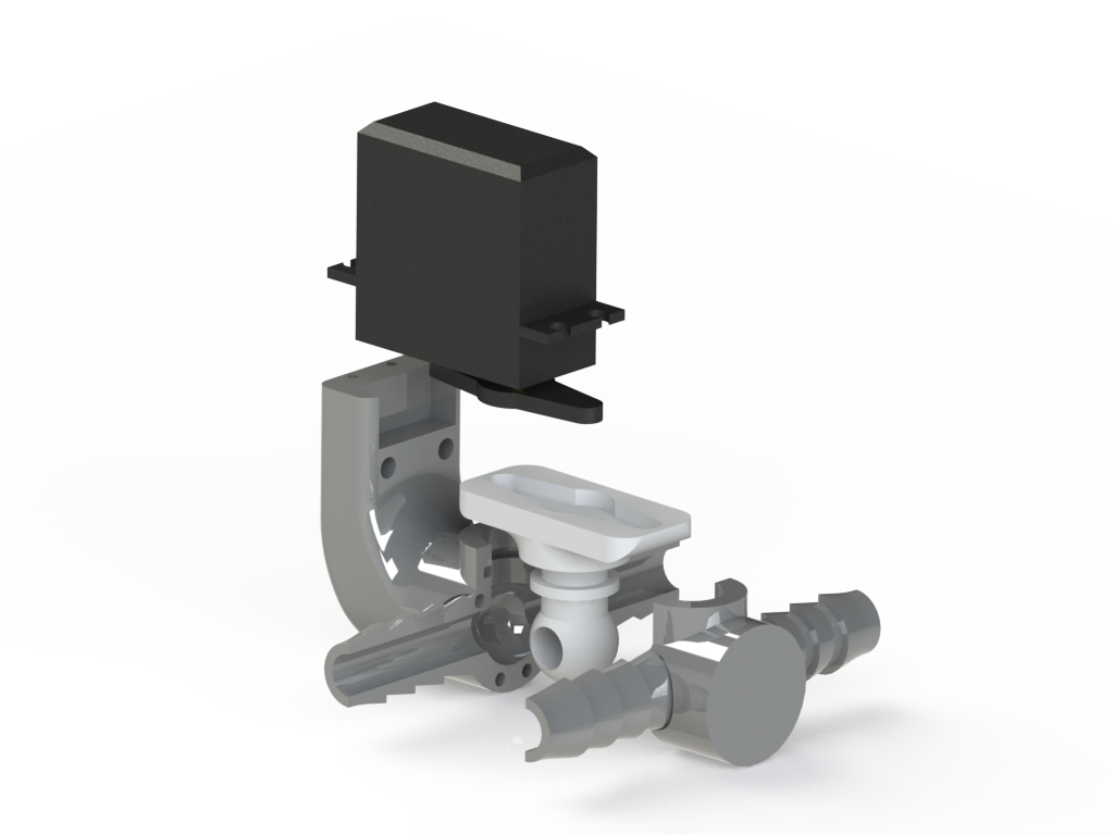
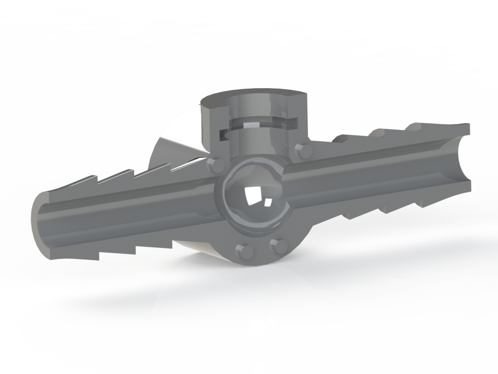
We printed a few different designs and, through a process of trial and error, the valve below was the one that seemed to work the best. It should be noted at this point that we are only trying to present the concept behind our valve and not selling a specific version of our model. Our drawing was optimised to work with a specific size of silicone tubing and a specific servomotor head, but the scalability and flexibility of the valve are remarkably high. The design can be easily modified to fit different pipes and it is hugely customisable.
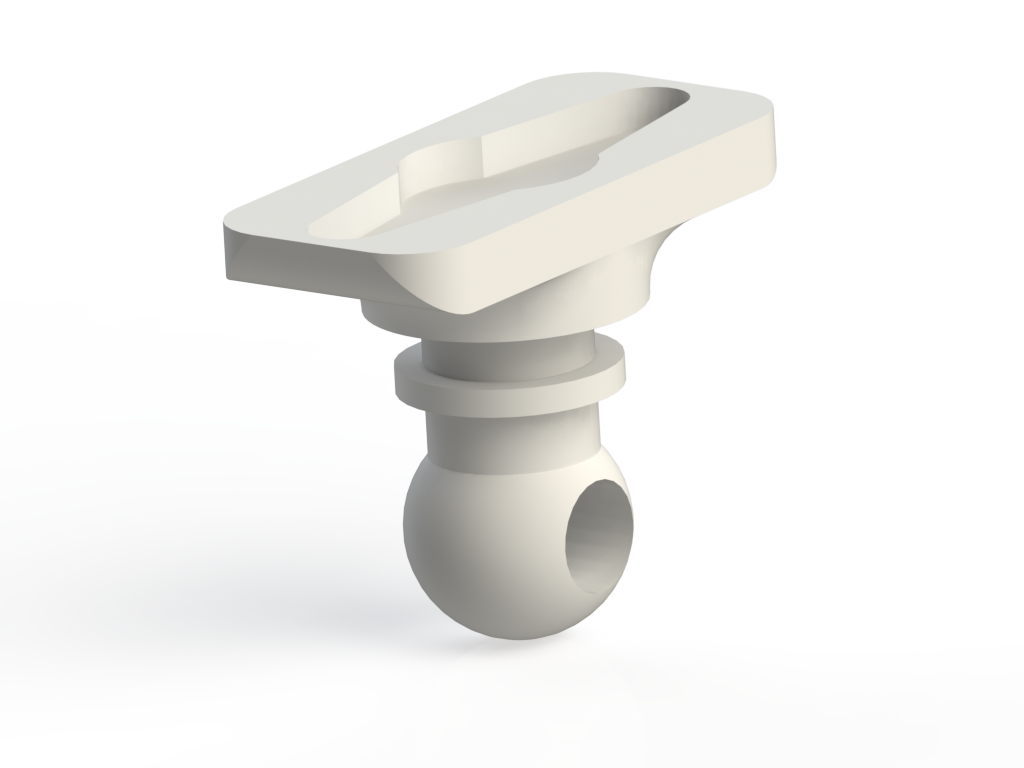
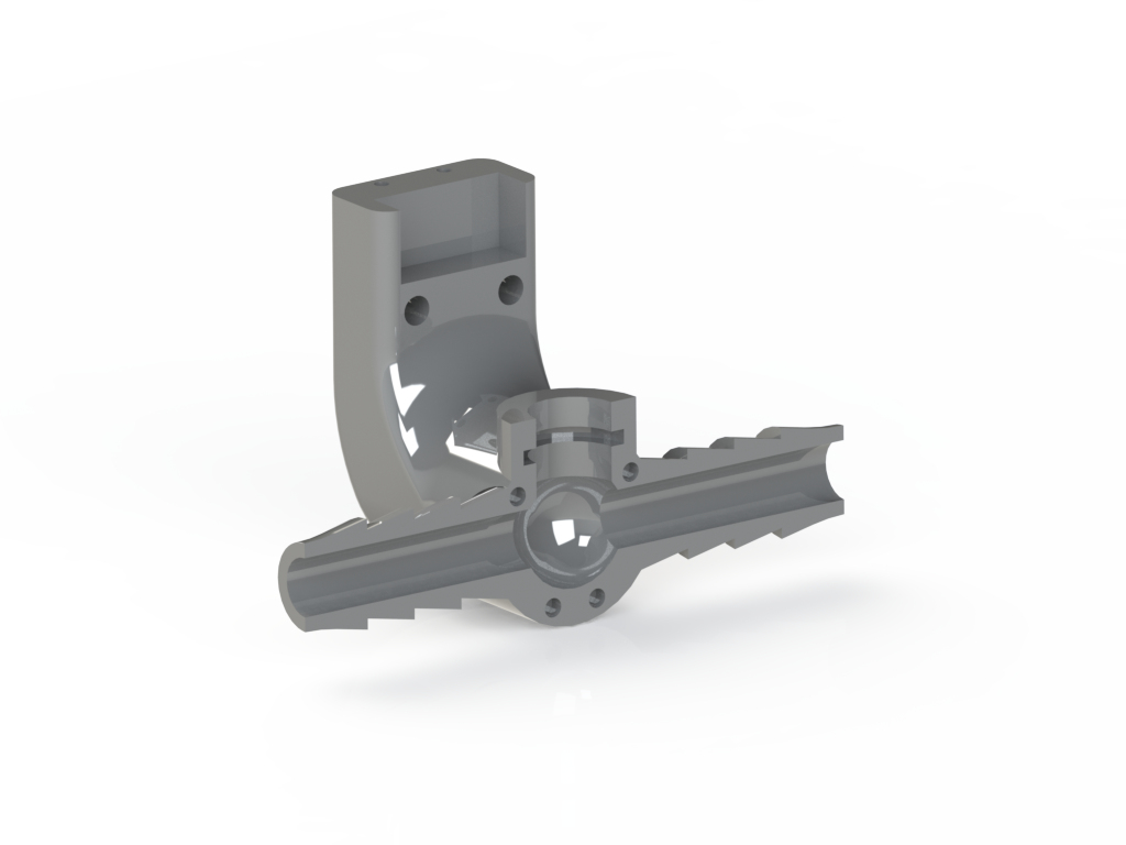
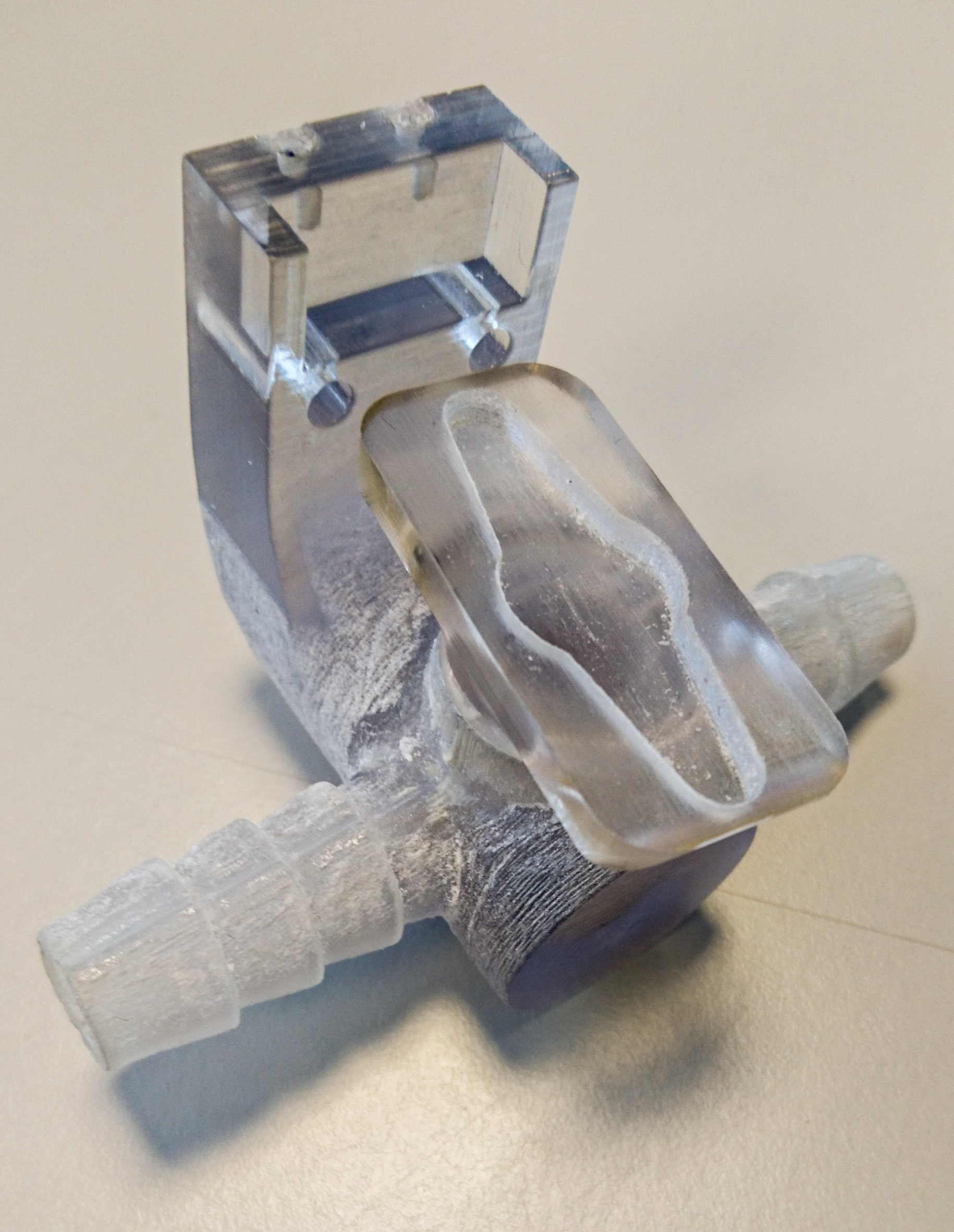
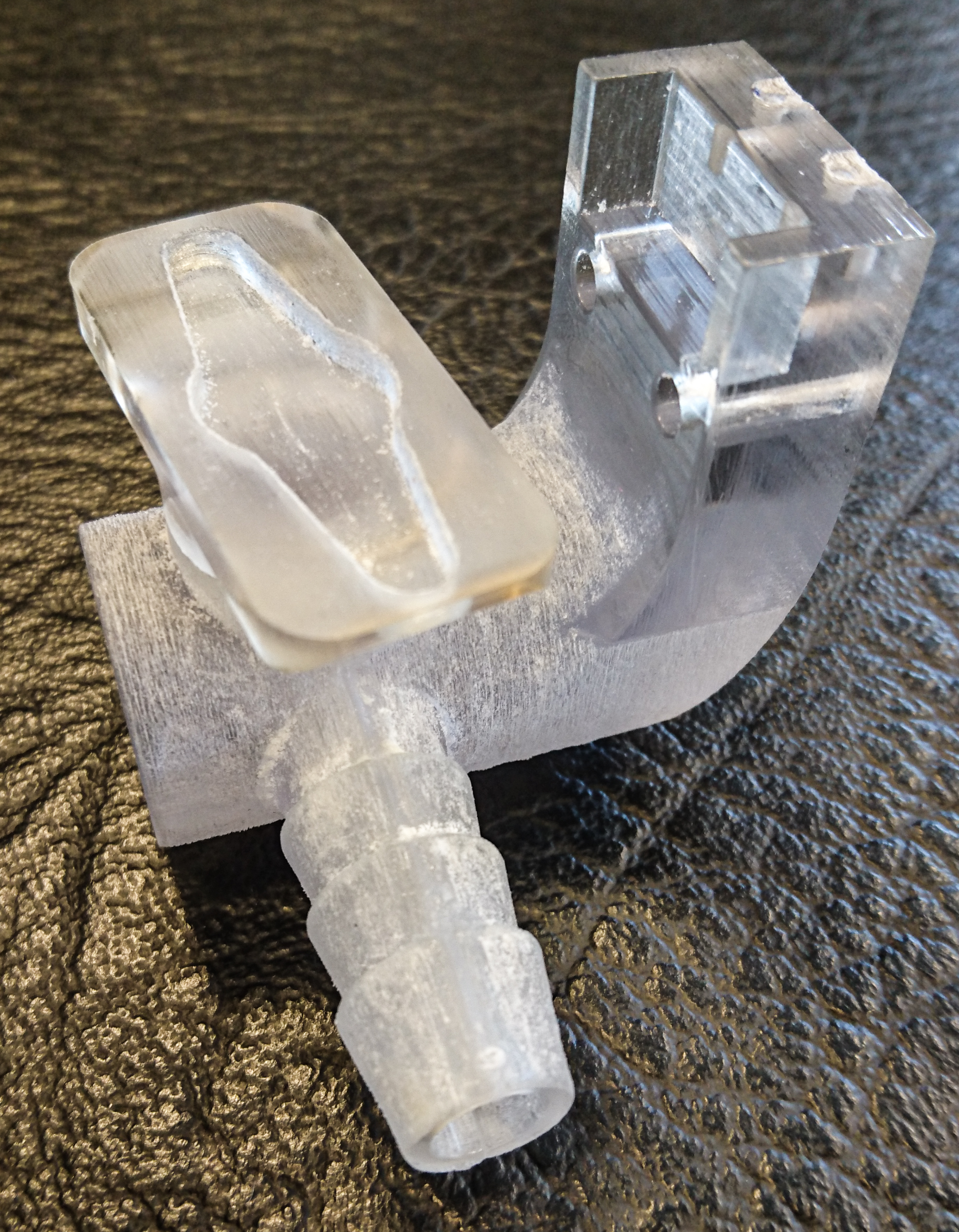
As shown in the pictures, the print consisted of three parts: the inner mechanism and the outer shell split into two halves. Our main goal was to make sure that the valve was completely water tight so we created an interference fit by making the diameter of the inner ball 100µm larger than the surrounding socket (the resolution of the 3d printer needs to be checked beforehand in other for this technique to be successful).
Once the print was finished (Print time: a few hours, Print cost: less than £10), we removed the support material and sanded down all the rough edges, frequently checking the fit between working parts. The inner mechanism was then lubricated and the two halves were joined together with epoxy glue (interdigitating features could be added for increased precision, but they are not strictly necessary). It is vital at this point that the mechanism is frequently moved in both directions because some of the glue might leak into the socket, effectively turning our precious valve into a worthless knick-knack.
The end result can be seen in the pictures below. A point worth mentioning is that the valve design needs to be adjusted according to the servomotor used. The valve turning motion can vary greatly depending on the fit between the components and the materials used. It can go from fairly smooth to quite stiff in a not very predictable manner, so an essential step is to make sure that the servomotor is powerful enough to overcome the torque caused by friction between the ball and the socket.
As a reference, we printed a few different prototypes using different machines (mainly SLA) and they all seem to work fairly well. If the 3d-printer allows it, a good finishing touch consists of treating the inside surfaces to guarantee a smoother finish and better water flow. All was courtesy of the Engineering department at the University of Glasgow.


