Team:MIT/Collaborations


Collaborations
Mammalian cell culture in microfluidic devices
Purpose
Integration of microfluidic devices has advanced considerably in quantitative biological research [1][2]. The timing of the fluid flow can be regulated with high accuracy because of the short response time of in-chip membrane valves (as quick as 1 ms)[1]. Moreover, with the aid of hydrogel, cells growing in microfluidics can be structured in three-dimensional geometries [1]. Therefore, cell culture performed in microfluidic devices could resemble in vivo conditions due to tight control of the microenvironment [2]. On the other hand, automation is another advantage of microfluidic technology. Instead of manual intervention, programmable fluid flows can automatically change chemical conditions of the culture environment. This feature would be particularly useful to examine dynamically changing systems [1]. The ability to precisely control fluid flows and chemical species as well as the automation of microfluidic technology are highly beneficial to future development of our project. Thus, the MIT iGEM team decided to collaborate with the Boston University Hardware iGEM team to develop a protocol for mammalian cell culture in microfluidic devices .
How does microfluidics benefit our project?
Collaboration
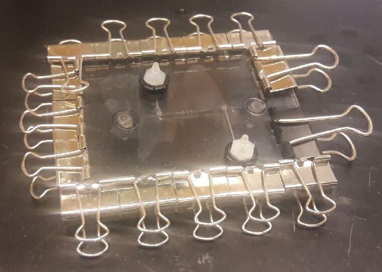
We collaborated with the Boston University Hardware iGEM Team to culture mammalian cells in their microfluidic devices. We started with the simplest experiment, which is growing HEK293 (Human Embryonic Kidney) cells in a microfluidic device. We performed the experiment with two different device models.

a = b = c = 400um ; Material: PDMS. Red for controlling air exchange. Blue for fluid channel.
Model 1
Microfluidic device
The device had 2 sets of channels, one for fluid flow (labeled blue in the diagram), and another one for air exchange (labeled red in the diagram). The first model did not have a chamber or specific region for cell culturing. The inlet and outlet were connected by a tube with uniform dimensions. This model, however, had rectangular cell traps along the channel.
Cell culturing protocol
- Harvest the cells were using the standard culturing protocol, and then resuspend in media to achieve 2E4cells/cm^2 seeding density.
- Sequentially sterilize and wash the channel with 1ml of 70% ethanol and 1xPBS by directly pipetting into the inlet.
- Through the same inlet, pipet 1ml of cells solution (1E6 cells/ml).
- Incubate the whole device with seeded cells at 37 degrees Celcius.

a = 3250um; b = 400um; volume of the chamber = ~ 4.4ul. Material: PDMS.
Model 2
Microfluidic device
Since we couldn't detect any cells under 10X light microscope (24 hrs post seeding) in the first model, we proposed several modifications to the device after doing some literature research, including:
- Creating a diamond-shape chamber specifically for cell adhesion. The increase in cross-section area along the channel reduces the flow rate of the fluid, making it easier for the cells to stick to the surface of the chamber
- Using a syringe pump to continuously replenish media inside the chamber after cell adhesion, preventing the media from drying out inside the chamber - which happened in model 1
- Including a 3D-printed frame, fitting the size of a 96-well plate, so that the whole seeding and culturing process can be monitored and captured using a microscope.
Cell culturing protocol
- Harvest the cells using the standard culturing protocol, and then resuspend in media to achieve 120E4 cells/ml seeding density.
- Clean and wash the chamber with 70% ethanol and 1x PBS.
- Use a 5mL syringe to load 1ml of media, 0.5ml of cell solution, and another media column to a 1.59mm diameter tube.
- Use a syringe pump to load media and cell solution in the tube to the device.

Results
Model 1

After 24 hours, the channel was completely dried out. The images didn't show any cells inside the channel even though cells in the control culture dish grew normally (image not shown), which was seeded at the same time with as microfluidic device. Since we couldn't check for cells inside the device right after seeding, We couldn't narrow down the main reasons for unsuccessful cell culturing in the microfluidic device. Thus, we decided to repeat the experiment (using model 2) with dynamic monitoring right from the seeding stage.
Model 2

Right after seeding, the cells were still in suspension; therefore, they all had spherical shape. After about 20 frames (190 minutes), they started to elongate and shifted out of focal plane. At the 26th frame (250 minutes after seeding), the cells were out of focus, which could indicate adhesion of the cells to the chamber's surface. The blue arrows point at cells showing evidience of mitosis, including appearance of two nuclei within a single cell and formation of the metaphase plate. Unfortunately, at the end of the video (after 350 minutes), the media within the chamber dried out, which has been a major problem for our experimental setup.
Read more about our collaboration on the BU Hardware Team's website
Testing pDEST mCherry
Purpose
As our way of giving back to iGEM, we created a screening tool for use in Gateway cloning reactions. In the past Gateway reactions have used the ccdB death gene as a negative selection tool to pick bacterial cultures that have successfully taken up a copy of the desired plasmid. However, due to a patent on ccdB and negative selection tools in Gateway, iGEM had to remove all ccdB-containing parts from their registry. Our screening tool, pDEST mCherry, uses red fluorescence to pick successfully transformed cultures. With this, we hope that iGEM will be able to distribute the parts that were discontinued, and mammalian work that relies on Gateway reactions will be significantly easier for future teams. While we used the pDEST mCherry successfully in our lab, we needed to test the clarity of the protocol we had written, and whether they would work in other labs.
Collaboration
We were thrilled to work with the Tufts University iGEM team in order to test our protocol, and our construct.
Results
The ligation reaction was successful. As can be seen on the plate that Tufts sent us, there are white colonies, and small red colonies.

Recombinases' sequences
Collaboration
At the begining of the summer, we had a discussion with the BU Wetlab Team to learn more about recombinases because some of their members and especially their graduate mentor - Ben Weinberg - had substantial experience working with recombinases. They specifically emphasized the issue of leaky expression of recombinase, resulting in high basal expression of output gene. Thus, during the conversation, we jotted down ideas for potential repressing systems, one of which were degradation tag and repressible promoters. However, the majority of their work with recombinase has been with tyrosine (Cre or FLP) family and done on E. coli. Thus, performing recombinase experiments in mammalian cell lines were unpredictable. Additionally, the BU Wetlab Team also helped us to obtain sequences for the recombinases and their equivalent recognition sites from Dr. Wilson Wong's lab.
Back to Experiments Home
REFERENCE:
- Mehling Matthias, and Tay Savas. Microfluidic Cell Culture. Science Direct 2014; 25:95-102.
- Komen Job, Wolbers Floor, Franke R. Henk, et al. Viability analysis and apoptosis induction of breast cancer cells in a microfluidic device: effect of cytostatic drugs. Biomed Microdevices(2008); 10:727–737