Christoph 90 (Talk | contribs) (→4. Testing the polymer) |
Christoph 90 (Talk | contribs) (→4. Testing the polymer) |
||
| Line 78: | Line 78: | ||
===4. Testing the polymer=== | ===4. Testing the polymer=== | ||
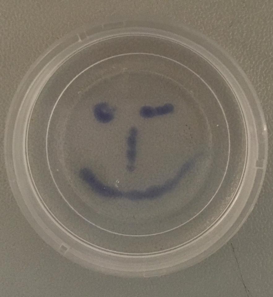
| − | [[Image:Muc16 Gallery 15.jpeg |thumb| | + | [[Image:Muc16 Gallery 15.jpeg |thumb|left|200px| '''Figure 5:''' Painting with the our recipe.]] |
Before filling it into our printer we did some experiments to prove the stability and ability to print in a precise manner. We were absolutely thrilled by the stability and integrity of our polymer. In fig. 5 we pipetted the recipe given above (with trypane blue for visualisation) into a Streptavidin solution of 11.4 mg/ml and were able to paint with our protein-cell-polymer. In the video above we shaked the polymer without any negative influence on the stability. | Before filling it into our printer we did some experiments to prove the stability and ability to print in a precise manner. We were absolutely thrilled by the stability and integrity of our polymer. In fig. 5 we pipetted the recipe given above (with trypane blue for visualisation) into a Streptavidin solution of 11.4 mg/ml and were able to paint with our protein-cell-polymer. In the video above we shaked the polymer without any negative influence on the stability. | ||
| − | + | <video width=29% style="float:right; margin-top : 15px; margin-bottom: 15px"; controls preload:"auto"> | |
| + | <source src="https://static.igem.org/mediawiki/2016/2/2c/Muc16_stability.mp4" type="video/mp4"> | ||
| + | Your browser does not support this video player.</video> | ||
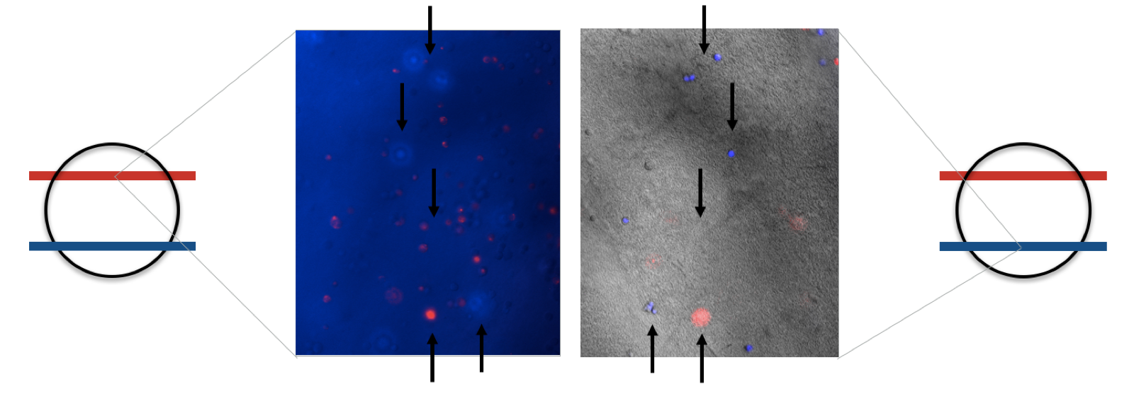
Furthermore we managed to produce stable layers of our ink. In one layer we mixed DAPI stained cells in the other our mRuby3 producing cells. We observed that the layers are sticking together and that both cell types are located in different focus levels (fig. 5). | Furthermore we managed to produce stable layers of our ink. In one layer we mixed DAPI stained cells in the other our mRuby3 producing cells. We observed that the layers are sticking together and that both cell types are located in different focus levels (fig. 5). | ||
Revision as of 10:55, 18 November 2016
Design: Why we chose the Avidin & Biotin affinity pair
| Affinity pair | Kind of interaction | Dissociation constant | Association rate |
| Avidin - Biotin | non covalent | 10-15M [1] | 55 440 |
| SpyCatcher - SpyTag | covalent | not applicable | far too slow for rapid polymerization |
| StrepTactin - Strep-tag II | non covalent | ~10-6M[2] | affinity is too low for a constant interaction |
Multivalency and avidity as major principles for polymerization
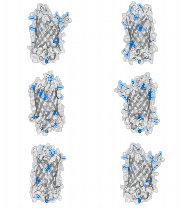
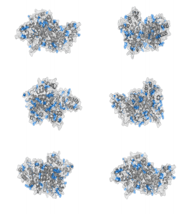
A nice point about the biotin - Avidin affinity pair is that biotin groups can be conjugated to any protein of choice that contains surface exposed amino groups. In the next line we have visualized amino groups in two proteins that we have used in our project as they are available in big amounts: enhanced Green Fluorescent Protein (eGFP, lower left) and Bovine Serum Albumine (BSA, lower right). The high number of 15 to 30 surface exposed amino groups in these proteins is a valuable advantage of this biotinylation approach as it results in highly biotinylated proteins as we also produced them in our "Proteins" sub-project. As we also synthesized the Biotin-NHS compound ourselves in our "Linker Chemistry" sub-project the supply with affordable material is also secured. Thus all components for this kind of polymerization were made accessible to the iGEM community.
Different polymers possible with biotINK polymerization
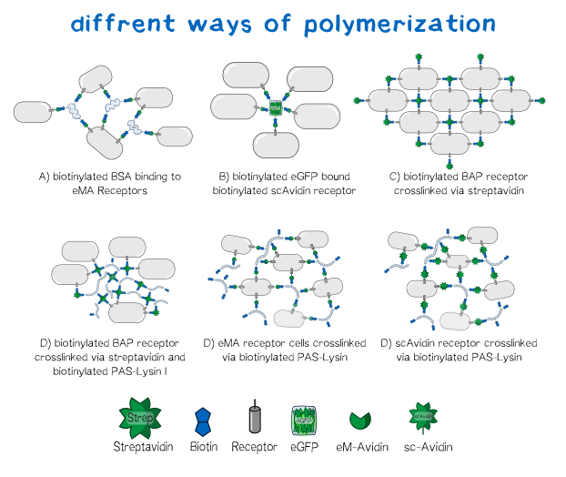
Since the basis of our polymerization reaction is the interaction of Streptavidin and its binding partner Biotin [3] we used biotinylated polymers to convey the polymerization between the cells. As one alternative for a linker molecule we biotinylated PAS-Lysin, which is an aminoacid sequence consisting of Prolin-Alanin-Serin repeats with a Lysin at about every 20th position [4] . As part of our bioink the polymer's biotin binds to the single chain Avidin, enhanced monomeric Avidin or respectively Streptavidin and is able to crosslink the cells. Additionally we tested other molecules as linkers like bovine serum albumin or eGFP to visualize the polymerization under the microscope. The principle in this case is the same as with PAS-Lysin, though the latter is the more promising linker for its large hydrodynamic volume,the presence of 20 Lysins for biotinylation, its high solubility and lack a folded secondary structure. [5] With a variable composition of the the bioink leading to customizable results in cell aggregation the DIY principle of BiotINK is emphasized. Apart from the linker variablity our BiotINK approach offers three different possible receptors expressed on the cell surface as key points for the polymerization. Each receptor binds biotin in a more or less different. In case of scAvidin and eMA these binding are cooperatively based on the streptavidin-biotin connection[6]. The BAP-receptor on the other hand is biotinylated via the co-expressed BirA and can be bound to Streptavidin available in the reservoir solution. In this case streptavidin itself can again bind to linkers or other biotinylated BAP-receptor cells.
All of the approaches pictured below should lead to a close mesh in which the cells are immobilized in such way that they can easily grow together and form three dimensional tissue.
Results: Polymerization experiments
Creating the perfect mesh
In order to characterize our cells concerning their biotin binding capabilities by taking a look at their polymerization behaviour after adding them to a medium, which is rich of biotinylated protein linkers. Since the expression of the two biotin binding receptor constructs was significantly higher than the expression of the biotin presenting one, we mainly used one of the biotin binding constructs, the scAvidin version.
1. Sticking the first Layer
Before performing polymerization experiments with these cells we wanted to make sure that the first printed layer is tightly fixed to the ground of the slide in order to unsure initial stability of the construct. Therefore we coated the slide with Poly-D-Lysine. These lysine residues exhibit again primary amines that can be biotinylated with our Biotin-NHS-Ester reagent. By this we provide an initial biotin layer that can be bound by our scAvidin presenting cells (fig. 2)
2. Figuring out polymerization conditions
The idea behind the polymerization experiments was to find the perfect conditions for the cells to stick together, concerning the right medium, concentration and biotinylation degree of the protein linker. The main components of all our polymerization experiments were svAvidin-construct-transfected TRex cells, biotinylated bovine serum albumine (BSA), both of them in the syringe and streptavidin in the reservoir. On a theoretic basis we would have expected polymerization in the syringe due to interaction of scAvidin-cells and biotinylated BSA. On a practical level we didn‘t observe it due to low cell density. Therefore we needed the aditional cross-linking capabilisties of streptavidin in the reservoir. Taking all our results together we are quite confident that biotinylated BSA could be placed in the reservoir (without any streptavidin) when more time for growing cells and therefore higher cell densities are available.
Our first experiments were not conducted with our printer, but under a fluorescence microscope for better analysability of the produced polymer. These tests showed that the polymerization effect is only dependent on three things:
- Cell density in the biotINK. Our cells carrying the scAvidin were the strongest binding ones.
- Concentration of Linker Proteins in the biotINK. Chemically biotinylated BSA, eGFP and PAS-Lysine were the most promising ones.
- Concentration of Streptavidin inside the printing medium.
Experiments showed that the concentration of biotinylated BSA in our biotINK is the limiting factor for polymerization. The Higher the concentration of BSA was, the more structural integrity of the "printed" polymer could be observed. This is likely due to diffusion rates and local protein concentration maxima upon printing.
3. Determing the optimal proteins concentrations
For approaching the optimal polymerisation we tried lots of different combinations and concentrations of linker moleclues, cells and reservoir conditions. Based on this empirical approach we identified the critial parameters on the macroscopic scale.
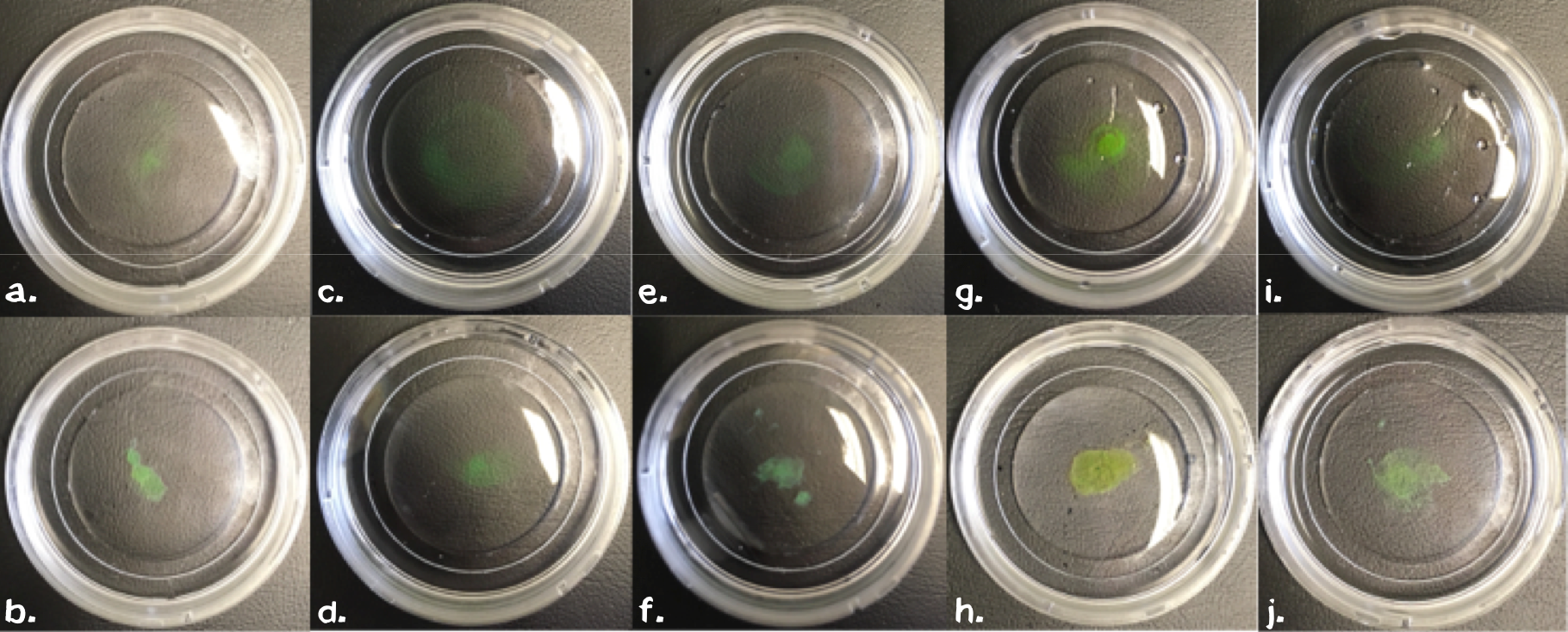
Building on this empirical approach we next evaluated the importance of these parameters for the polymer by leaving out one of each component in subsequent steps. Therefore we mixed sedimented cells, chemically biotinyltaed BSA (11 mg/ml), EGFP (3 mg/ml) or chemically biotinylated PAS-Lysine (10 mg/ml) in different settings (fig. 4). For samples without biotinylated GFP we mixed 5 µl 1 mM non-biotinylated GFP into the samples to ensure good visualiszation. All samples were carefully swireled to ensure that agglutination is not due to an artefact.
The comparission between the upper pictures in figure 4, which correspond to PBS in the reservoir and the lower one with Streptavidin (11.4 mg/ml) in the reservoir, clearly shows that streptavidin induces polymerization. As mentioned before biotinyliated BSA or PAS-Lysine are mandatory for polymerisation. Neither cells (fig. 4d), nor GFP (fig. 4f) on its own are sufficient. By directly comparing the sample in fig. 4b with the one in fig. 4h we stated that both linker proteins either BSA or PAS-Lysine work quite good. The comparision of fig. 4b with fig. 4j shows that pre-polymerization with a small amount of Streptavidin improves the stability of the polymer, nethertheless it is not mandatory. Directly printing in a Streptavidin reservoir is sufficient for polymerization.
All in all we developed a recipe for the perfect mesh:
• 6/10 volume parts biotinylated (with 40x molar ecess) BSA, 11 mg/ml or biotinylated PAS-Lysin 10 mg/ml
• 0.5/10 volume parts biotinylated (with 40x molar ecess) GFP, 3 mg/ml, just for better visualisation
3.5/10 volume parts gravity sedimented scAvidin-cells, this might correspond to about 10 mio. cells per ml
4. Testing the polymer
Before filling it into our printer we did some experiments to prove the stability and ability to print in a precise manner. We were absolutely thrilled by the stability and integrity of our polymer. In fig. 5 we pipetted the recipe given above (with trypane blue for visualisation) into a Streptavidin solution of 11.4 mg/ml and were able to paint with our protein-cell-polymer. In the video above we shaked the polymer without any negative influence on the stability. <video width=29% style="float:right; margin-top : 15px; margin-bottom: 15px"; controls preload:"auto">
<source src="https://static.igem.org/mediawiki/2016/2/2c/Muc16_stability.mp4" type="video/mp4">
Your browser does not support this video player.</video>
Furthermore we managed to produce stable layers of our ink. In one layer we mixed DAPI stained cells in the other our mRuby3 producing cells. We observed that the layers are sticking together and that both cell types are located in different focus levels (fig. 5).
Applying The Technology
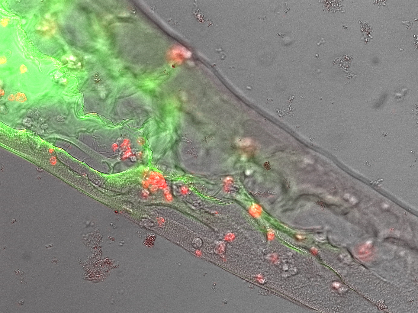
Next we asked wether we were just polymerizing protein or if our receptor construct is functional and our cells are „sticky“. Therefore we needed to see that the avidinylated cells attach to the biotinylated GFP/BSA polymer. We drew some lines of our perfect mesh recipe into Streptavidin solution and watched the polymer under the microscope. Here were saw a well structured shape with cells in it (fig. 3). Upon heavily shaking the microscopy slide the polyer is shaking from side to side but not breaking and most interestingly: the cells are shaking with the polymer but not dropping out of it. This becomes especial interesting when mixing our avidinylated cells with normal cells. Most cells are encapsulated in the protein-matrix like in the conventional Bioprinting process, but upon shaking the non-engineered cells drop out of the matrix while our cells bound in the matrix. This gives a clear hint on the much higher stability of bioprints that are based on our approach.
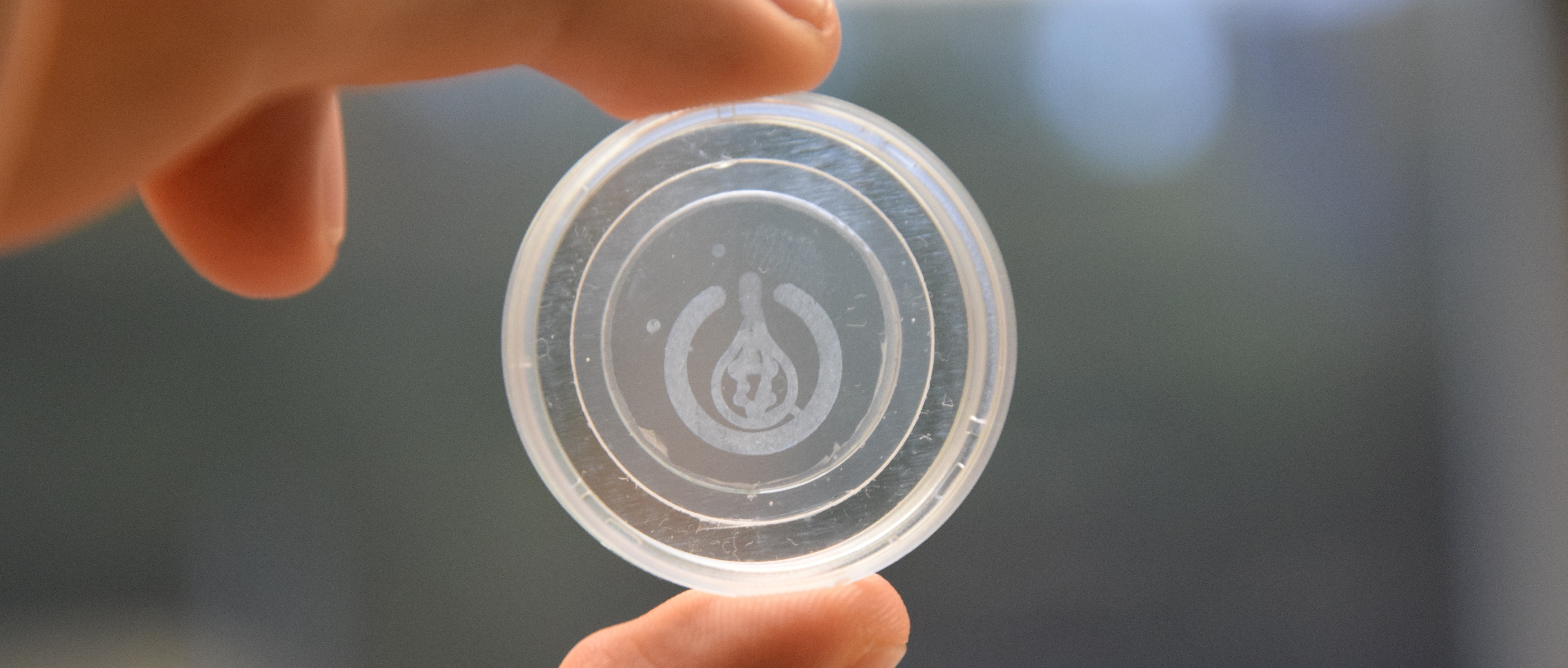
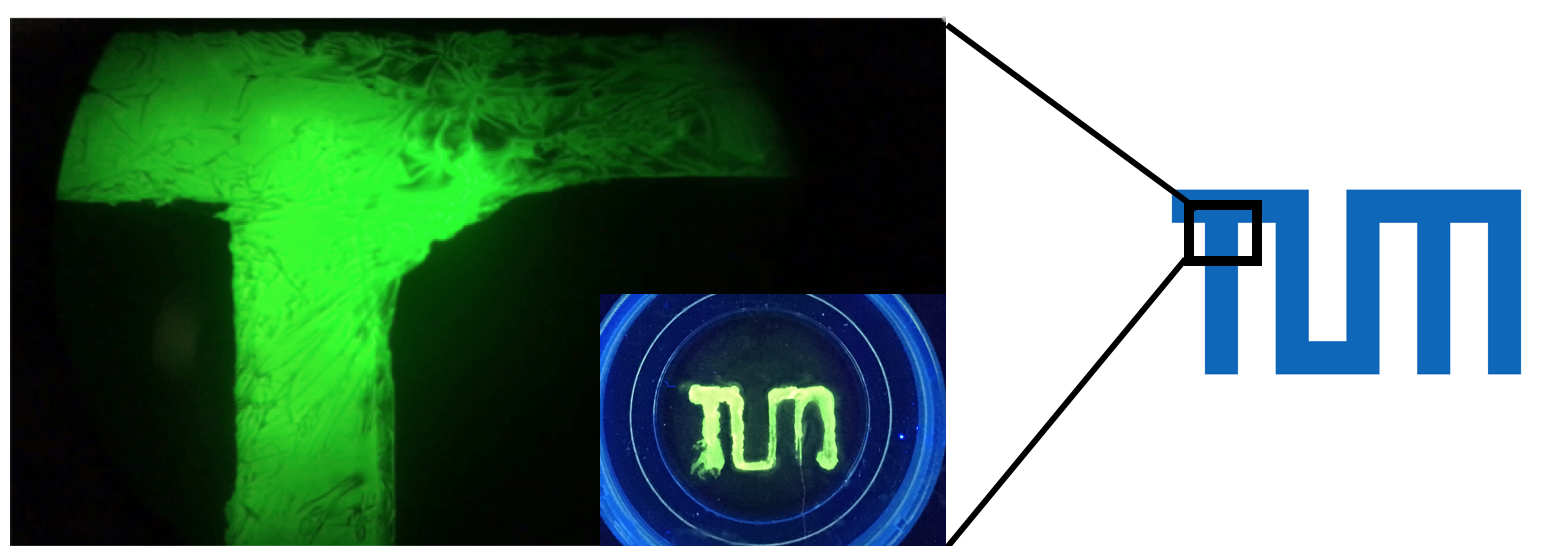
After figuring out all the necessary parameters we applied our technology to print our cells in different pattern. So finally we managed to transfer all these experiments into practice: we printed the TUM logo and our own logo with a ink made of biotinylated proteins and cells (fig. 4)! Especially when magnifying a part of the "T" the precision of our approach becomes clearly visible.
Sticky cells in the Micromanipulator
To get a clearer view on how the cells polymerize we wanted to see the actual polymerization event and how the cells stick to each other. In order to do so we used a micromanipulator for ejection of single cells. We compared the ejection of our biotINK in Streptavidin solution with the ejection in phosphate buffered saline (negative control) to make sure that, if polymerization occurs, it is because of an specific interaction of the cells with biotinylated BSA and streptavidin.
It was very interesting to see that there really is a difference between the two experiments in a way that the biotINK, ejected in streptavidin, contrary to the one ejected in PBS, does show polymerization of cells.
Summary of Archivements and Future Work
First of all we developed a new hydrogel that is composed of avidin and biotinylated proteins. This hydrogel has some major advantages compared to available hydrogels like polymerization in water, fast and stable polymerization-process and a naturally occurring matrix fully build of proteins. We managed to encapsulate cells in this gel and print them in defined structures.
But our project aimed to develop a hydrogel-free bioprinting approach. We were running out of time to produce the amount of cells to fully validate our idea. Therefore we utilized some workarounds like mixing engineered with non-engineered cells and shaking the polymer to prove dropping out of non-engineered cells. Based on these results, proving that our engineered cells strongly bind biotin and the fact that our proteins are biotinylated (see other results pages) we are quite confident to state that our approach is working. We would really be excited to see wether this approach works with high cell-densities because this is the major limitation of todays bioprinting technology. Here the cell density is limited to the amount of embedding hydrogel that is needed for efficient polymerization. We don't need any hydrogel therefore we think 100% cell density might work even better then low cell densities. Another aspect of our approach is that we can control every single component of the molecular principle and can therefore steer the whole printing process on every level (fig. 5). These aspects might take bioprinting to a whole new level, getting closer to the final goal of organ printing.
Next steps will be to evaluate factors like stability of the printed tissue, cell viability and how to influence differentiation processes inside the printed tissue.
References
- ↑ Green, N. M. (1963). Avidin. 1. The use of [14C] biotin for kinetic studies and for assay. Biochemical Journal, 89(3), 585.
- ↑ http://www.iba-lifesciences.com/
- ↑ Korndörfer, I. P., & Skerra, A. (2002). Improved affinity of engineered streptavidin for the Strep‐tag II peptide is due to a fixed open conformation of the lid‐like loop at the binding site. Protein science, 11(4), 883-893.
- ↑ Breibeck, J., Serafin, A., Reichert, A., Maier, S., Küster, B., & Skerra, A. (2014). PAS-cal: a Generic Recombinant Peptide Calibration Standard for Mass Spectrometry. Journal of The American Society for Mass Spectrometry, 25(8), 1489-1497.
- ↑ Schlapschy, M., Binder, U., Börger, C., Theobald, I., Wachinger, K., Kisling, S., ... & Skerra, A. (2013). PASylation: a biological alternative to PEGylation for extending the plasma half-life of pharmaceutically active proteins. Protein Engineering Design and Selection, 26(8), 489-501.
- ↑ Hyre, D. E., Le Trong, I., Merritt, E. A., Eccleston, J. F., Green, N. M., Stenkamp, R. E., & Stayton, P. S. (2006). Cooperative hydrogen bond interactions in the streptavidin–biotin system. Protein science, 15(3), 459-467.


