Team:UMaryland/Model
</div> </div>


Background |
Pathway |
Optimization |
Results |
|---|
Background
The Modeling portion of the UMaryland iGEM project proposes specific adjustments to the expression levels of enzymes in the methane digestion pathways. Our modeling efforts focus on ensuring the viability of our engineered organism, and optimizing the efficiencies of our pathways. Along the way, our team encountered stumbling blocks that we would like to illuminate for iGEM teams in the future. Incorporated into our modeling page is a concise guide on getting started with the Matlab applet, Simbiology, to model simple metabolic pathways. If you have no interest in this guide, please feel free to optimize your time by skipping over the purple text.
Simbiology is a tool that enables teams with variable modeling backgrounds to build pathway architectures by using a simple drag and drop interface. Although Simbiology is an extremely useful and intuitive tool, it does require some experience to navigate, and it does have its errors; but more on that later. The first step is to open Simbiology by typing “simbiology” into the Matlab command window, then hitting enter.
 Simbiology allows you to drag these elements onto an interface to design your model. For our model, we mainly used the “species” icon and the “reaction” icon.
To begin drawing your metabolic pathway, drag and drop a “reaction” icon, located on the left hand sign of the window, onto the blank canvas covering the right half of the window. Then double click on the small orange reaction circle that you placed, and enter your chemical reaction into the block property editor by replacing “null -> null” with your balanced formula. Enzymes are included in the balanced formula. Make sure your enzyme is represented as both a reactant and a product. Clicking out of the Block Property Editor will create species with arrows pointing into your reaction and arrows pointing out of your reaction. Enzymes are connected to the reaction by a dotted line, representing an intermediate that is not consumed or produced by the reaction. You may place as many reactions and species onto the canvas as you would like. If you would like an example model architecture, our pathways are shown later.
Creating the Pathway Architecture
The models for our formate and fructose pathways each consist of two compartments, four reactions and 14 or 15 species, respectively. The initial goal for our project was to produce a co-culture of cells consisting of “sMMO Cells” that produce methanol and “Formate/Fructose Cells” that detoxify methanol, all in an effort to completely biodegrade methane. The first compartment in our model shown below is the “sMMO Cell” that converts methane to methanol, which travels to the second compartment of our model, either the “Formate” or “Fructose Cell.” Each species represents a different molecule involved in our pathway. The architecture for our Formate pathway displays a progression of compounds starting at methane and ending at carbon dioxide. In all, this pathway is facilitated by four enzymes.
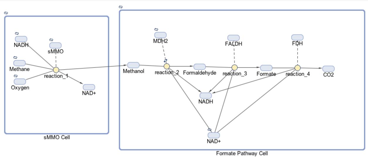
The first half of each pathway is identical. The first enzyme used in each pathway is sMMO, which catalyses the oxidation of methane to methanol while simultaneously oxidizing NADH to NAD+. Both pathways then proceed to oxidize methanol to formaldehyde, which is a reaction catalyzed by the MDH2 enzyme.

Once formaldehyde is produced, the two pathways begin to differ. In the Formate Pathway, formaldehyde is first oxidized to formate, which is then oxidized to carbon dioxide by FALDH and FDH enzymes respectively. In the Fructose Pathway, formaldehyde is incorporated into a 5 carbon sugar by HPS to make D-arabinose 6-phosphate, a 6 carbon sugar. PHI then converts D-arabinose 6-phosphate into D-fructose-6-phosphate, which is a substrate of glycolysis.


© University of Maryland iGEM 2016