Team:EMW Street Bio/Hardware/Incubator

Biota Beats - by EMW Streetbio

Incubator

Building the Enclosure

3D CAD Modelling

This is an incubator designed to be retrofitted onto an existing record player. Since our goal is to represent the growth of cultures through audio, the design criteria required:

  • Detection: Visually detect the growth of an entire petri dish (the size of a vinyl record) using a camera without occlusions
  • Compatibility: Ensure the heat generation from the incubation will not degrade the enclosure and produce unwanted molecules/gas
  • Accessible: Easily change out by-hand the culture plates; easily monitor the plates
Utilizing Rhinoceros 3D modelling software, we modelled our record player.

Based on the specifications of our camera module, we calculated the minimum height that is required in order to image a 12” petri dish based on the field of view of our camera.

Specifications of our camera module:

  • Angle of View: 54 x 41 degrees
  • Field of View: 2.0 x 1.33 m at 2 m
  • Full-frame SLR lens equivalent: 35 mm
  • Fixed Focus: 1 m to infinity
  • Max frame rate: 30fps

We confirmed our calculations by conducting an initial test:


Fabrication

Vector paths were extracted from our 3D model and then imported into CoralDraw for laser cutting of acrylic sheets.

Heating Element

Planning

We determined that the heating element should be below the dish itself to provide semi-localized heating for incubation. This ensures that the enclosure will not undergo degradation or overheating.

The goal was to maintain an agar plate at 37C while retaining access to the top. The enclosure was not well insulated, but adding insulation would interfere with existing functionality. Therefore, heat was applied immediately underneath the plate.

Nichrome wire was used as the heating element, and the wire was insulated from the existing aluminum plate with Kapton. A thermistor provides the feedback path and was bonded to the aluminum plate.

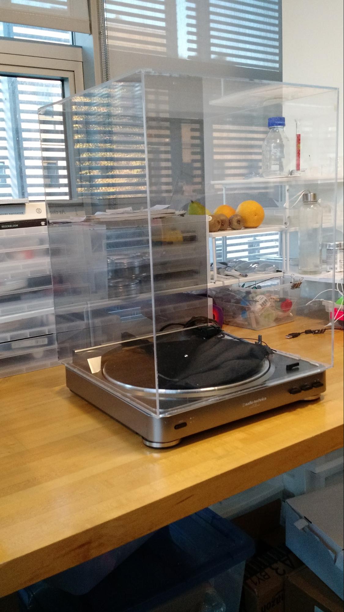
Once fully integrated, the incubator tray is nearly invisible

Calculations

The enclosure's leakiest heat path is through a 3mm thick acrylic wall with almost one square meter of surface area. This provides very little material insulation, so the loss path is dominated by convective cooling.

  • Conductivity Estimate: 65 Watts per Kelvin
  • Convection Estimate: 20 Watts per Kelvin

To maintain the entire enclosure at 37C, the heater needs to push 250 Watts. This is 13 Amps out of the 18V supply and does not include any headroom for getting up to 37C- just maintaining an existing temperature.

Reducing the scope to only maintaining the plate allows us to use the trapped air as insulation. A second convection barrier with a much smaller surface area is estimated to be 0.025 square meters. This becomes about 0.3 Watts per Kelvin. Much more reasonable!

The new power requirement is therefore ~50 Watts, allowing for some headroom and is just under 3 Amps from the 18V supply and a 6.5 Ohm heater element. For 5 Ohms, 15 inches of Nichrome were cut, and resistance was verified by measuring a programmable power supply across it. Nichrome has a positive temperature coefficient, so it draws less power when it is hot, so a length adjustment was needed to return it back to 50W output at temperature.

Heater Element Construction

The next step was to attach the Nichrome element to the aluminum plate. High-temperature Kapton tape was ordered but hadn't arrived yet. Knowing full-well this was a terrible idea, electrical tape was tried. It burned immediately.

Rebuilt with high temperature Kapton tape, the heater element was tested at 4x the intended power for 5 minutes and held up surprisingly well. There were no shorts, but the areas that were holding the Nichrome in tension had some damage.

The third iteration added small ceramic beads to the Nichrome element. The beads electrically and thermally isolated the Nichrome while dispersing the pressure on the Kapton tape. It is a much lower fire hazard as it now takes longer for the effects to become noticeable.

Regulator

This is a simple bang-bang temperature regulator using an ATTiny, a thermistor, and a FET. If the measured temperature is below 35C, it turns the heater element on. Once it is above 27C, it turns the heater element off. Any temperature outside of 20C - 40C means that something has broken, so it turns everything off until it is power-cycled.

R3/J3 are the thermistor, forming a divider with R4. T1 is the control FET, controlling R2/J2. IC1 is the ATTiny. IC2 is a voltage regulator to knock the input power down to 3.3V for the ATTiny.

Final Assembly

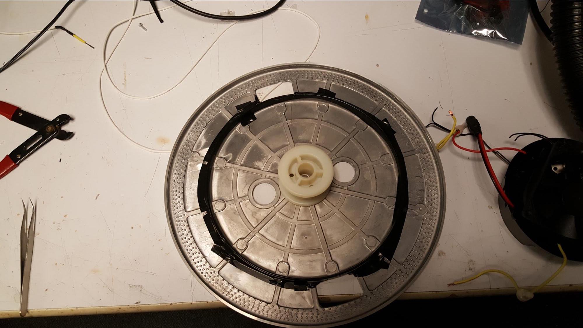
Power wire from board is snaked up through an existing hole. Additional reinforcement. 
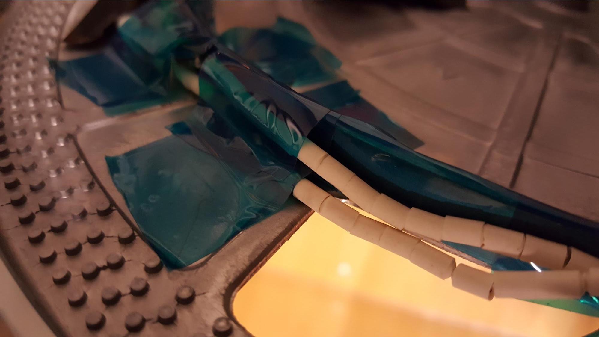
Heating element connected and attached