Contents
- 1 Introduction
- 2 System
- 3 Result
- 4 Application
Introduction
Gene expression controlled by external induction has been widely studied in synthetic biology. In recent years, expression control without an induction, enabling cells to spontaneously change their gene expression, has also been investigated. For example, iGEM SYSU 2015 designed a system allowing a specific gene to be expressed after a certain time using recombinase. However, in this system, it is difficult to estimate when the gene expression will change. Moreover, since the DNA sequence itself is changed, the genes expressed is irreversible.
We thus decided to this year, design a genetic circuit which enables E. coli to change its gene expression every cell division and make the gene expression state loop within a certain number of divisions.
Basic biology would tell us that if an E. coli expressing GFP divides, the next generation would also express GFP (not suddenly RFP or CFP!). Therefore, the idea of making use of the system to create cells which will be expressing only GFP in the first, only RFP in the second, only CFP in the third generation and loop back to expressing only GFP in the fourth sounded very exciting. We first modelled the system and our results demonostrated that the gentic circuit can function as we designed. We chose the main genetic components to be used in our system (a Toehold switch, sigma factors, a cell cycle dependent promotor Pnrd, and inducible promoter PBAD) based on our modelling results and experimentally characterised the parts.
Since it is possible to make E. coli express a specific gene only after a definite number of divisions, the system can be further applied in synthetic biology and in field. For instance, a kill switch programmed to make E. coli die after a certain number of divisions can be constructed. Furthermore, by utilizing the loops enabled in our system, even for commands requesting a certain output after a large number of cell division, not so many genetic components are required (refer to the application page for details of the design).
[1] Team:SYSU CHINA. (n.d.). Retrieved October 16, 2016, from https://2015.igem.org/Team:SYSU_CHINA/Project
System
By designing a genetic device that shifts the dominantly expressed protein among GFP, RFP and CFP every cell cycle, our system can realize E. coli that in turn gives out green, red, blue (and green again) fluorescence. To understand how it works, let’s first take a look at the individual components we used. These include Toehold Switch, sigma factors, Pnrd, and PBAD.
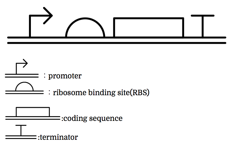
Genes are shown in the diagram below, where left represents the upstream.
Toehold Switch
The Toehold Switch is a translational regulation system which takes advantage of the bonding between specific transcripts. Genes downstream of the Toehold Switch on a mRNA cannot be translated without the existence of specific trigger RNA.
Ribosomes cannot bind to the toehold RBS under normal conditions. Therefore, proteins cannot be made because mRNAs cannot be translated even when the gene is transcribed. For a ribosome to bind to a toehold RBS, the existence of a specific short RNA named trigger RNA is necessary.
![]()
The previous gene which the toehold RBS stops transcription comes to the state below under the existence of the trigger RNA, and will be translated. Functioning DNA is represented as yellow one.
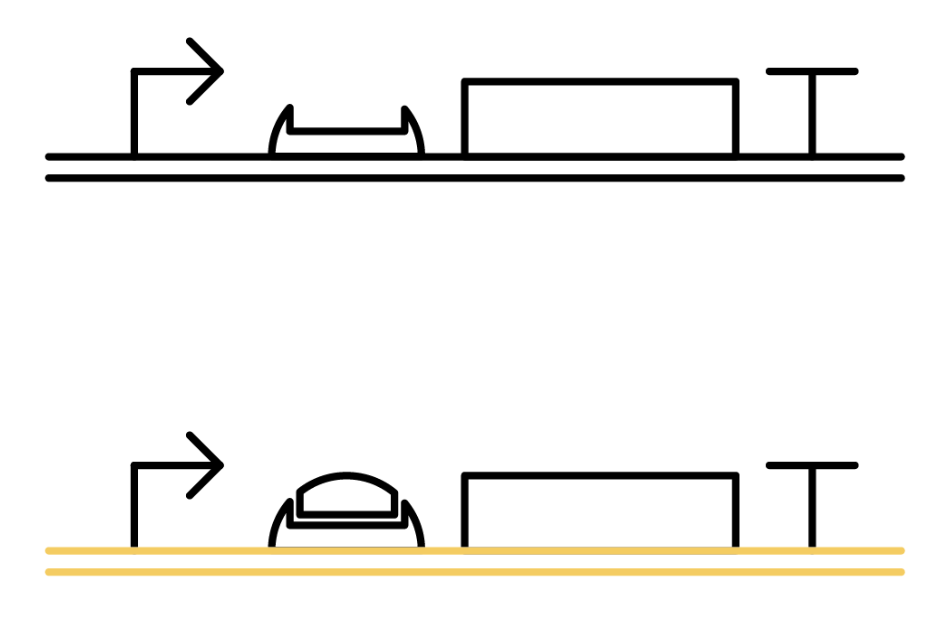
Why ribosome cannot bind to toehold RBS?
Specific sequences, called ribosome binding site (RBS) to which ribosome binds exists on mRNAs . Inserted with specific complementary sequences on both upstream and downstream of RBS, mRNA forms a hairpin structure that encloses the RBS. Ribosome therefore cannot bind to toehold RBS and thus genes downstream unable to be translated. This kind of RNA is called switch RNA. However, the hairpin structure of a switch RNA can be broken by what is called the trigger RNA, which includes partially complementary sequence with the switch RNA and thus makes the translation of downstream genes possible.
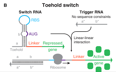
Figure 1 [1]
Sigma Factor
The promoter below (sigma promoter) works only under the existence of sigma-factor, which binds to and then activates the promoter. However, anti-sigma factors also bind to sigma factors, which competitively inhibit sigma factors from functioning.
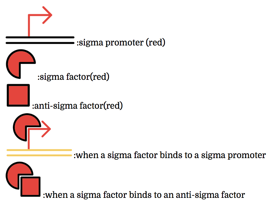
Detailed Info
The sigma factors are promoter recognition subunits of RNA polymerase. A sigma factor is associated with a part of promoters. A sigma factor recruits RNA polymerase to its corresponding promoter and initiates transcription. Sigma factors have great variety. Some of sigma factor-promoter pairs have one-to-one correspondence. Thus, if only sigma factors which have one-to-one correspondence are used, a transcription activating system in which a sigma factor activates the transcription only from corresponding promoter can be made.
Anti-sigma factors are proteins which are related to transcriptional control mechanism by sigma factors. An anti-sigma factor inhibits the binding between RNA polymerase and sigma factor. Consequently, anti-sigma factors repress the transcription from the promoters which sigma factors initiate. In the same way as sigma factors, anti-sigma factors have great variety and some anti-sigma factors prevent only a specific sigma factors from transcriptional control. Therefore a transcription control system (i.e. not only activating but also repressing) can be constructed by using specific sigma factors and anti-sigma factors which have one-to-one correspondence.[2](words underlined were grammatically modified from the original)
Multiple combinations of sigma factors, sigma promoters, and anti-sigma factors exist. Every factor we used functions exclusively within its combination and does not bind with factors of other combinations. In other words, they do not crosstalk. To make this easier to understand, factors and promoters of the same combination are presented with the same color.

Pnrd
Pnrd, another kind of a promoter, works only during cell division.
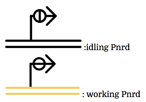
PBAD
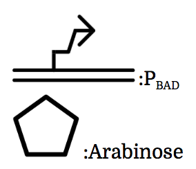
We also installed a promoter called PBAD, which works only under the existence of arabinose, drawn as pentagon in the chart.
We used part [http://parts.igem.org/Part:BBa_K2070018 BBa_K2070018] and [http://parts.igem.org/Part:BBa_K2070016 BBa_K2070016] as toehold switch, [http://parts.igem.org/Part:BBa_K2070001 K2070001], [http://parts.igem.org/Part:BBa_K2070009 K2070009], [http://parts.igem.org/Part:BBa_K1461005 BBa_K1461005] as sigma factors, [http://parts.igem.org/Part:BBa_K2070002 K2070002], [http://parts.igem.org/Part:BBa_K2070010 K2070010], [http://parts.igem.org/Part::BBa_K1461224 BBa_K1461224] as anti-sigma factors, [http://parts.igem.org/Part:BBa_K2070000 K2070000], [http://parts.igem.org/Part:BBa_K2070008 K2070008],[http://parts.igem.org/Part:BBa_K1461002 BBa_K1461002] as sigma promoters, [http://parts.igem.org/Part:BBa_K847211 BBa_K847211] as Pnrd, and [http://parts.igem.org/Part:BBa_I0500 BBa_I0500] as PBAD.
Now we’ve seen the 4 components and they will help us understand what our team wants to make. Let’s go to the journey to the gene constructions and systems.
Gene Constructions and Systems
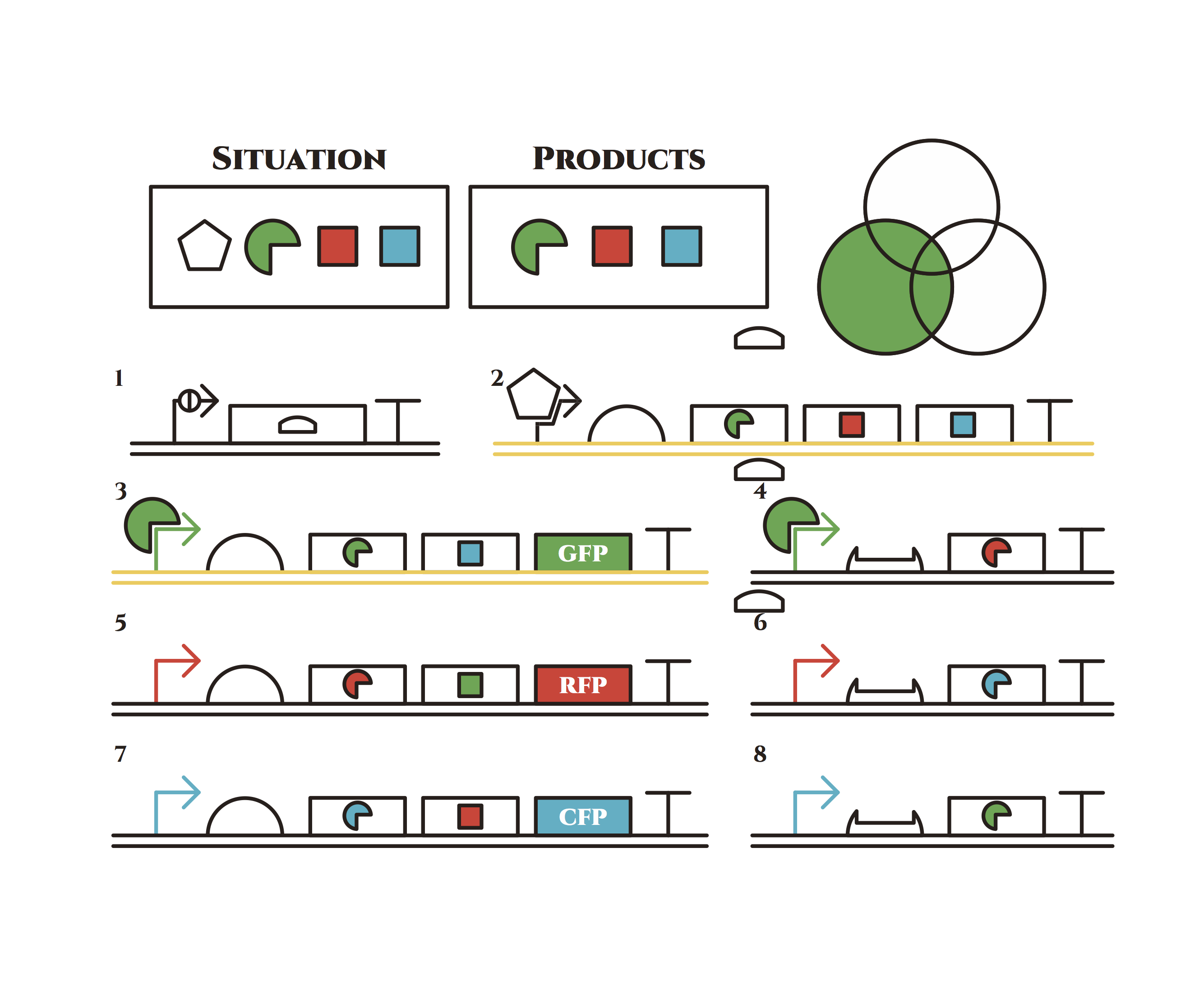
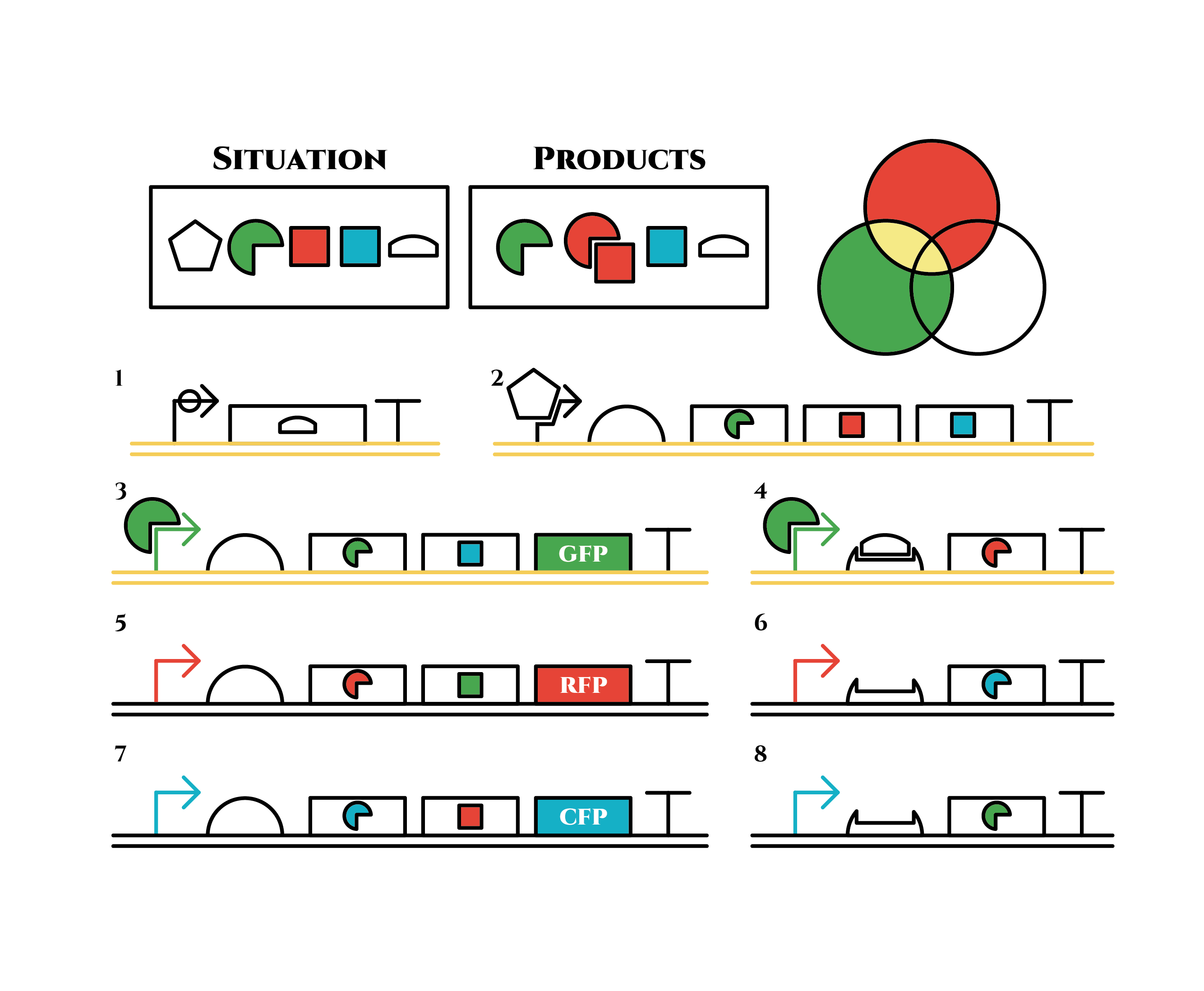
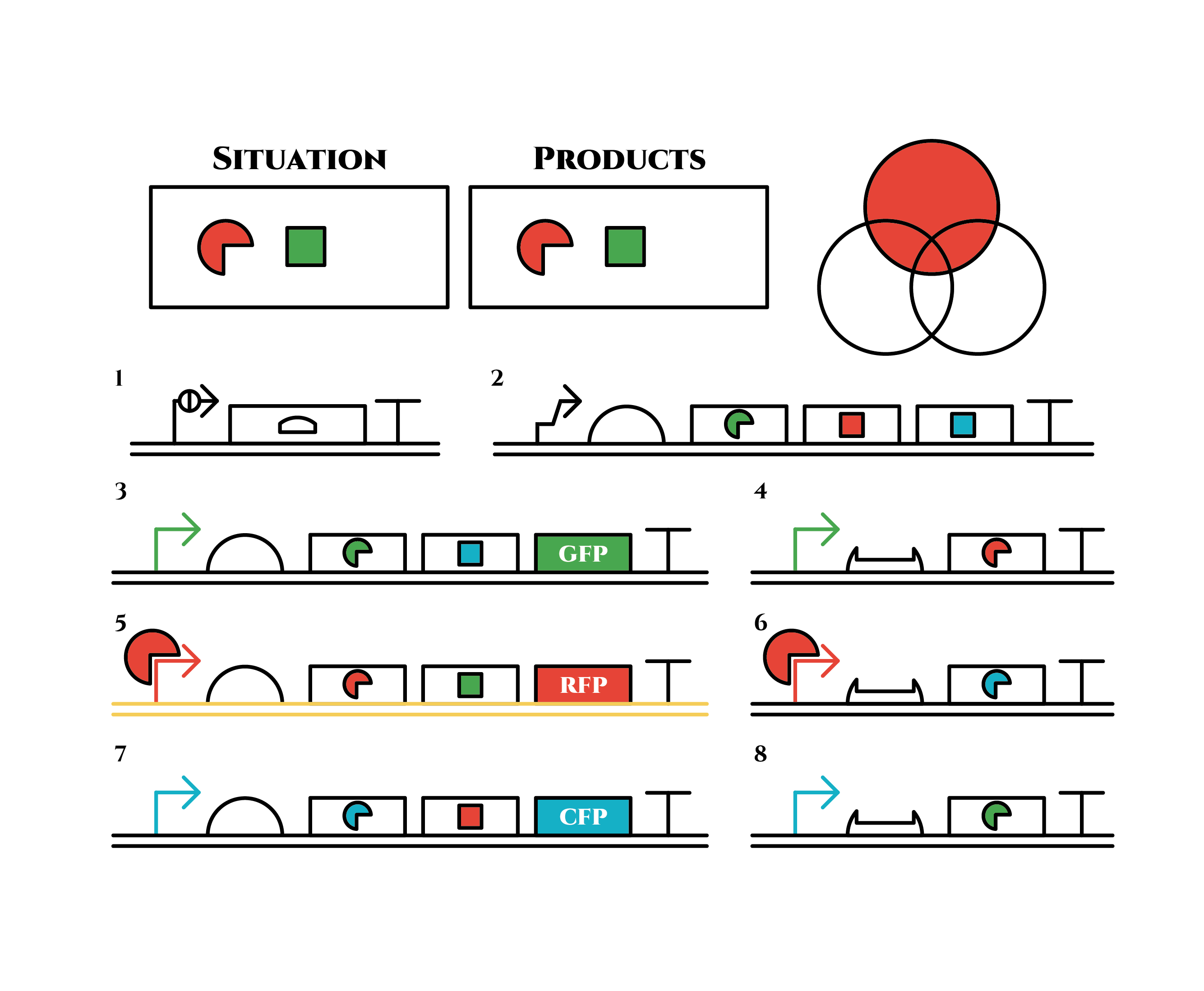
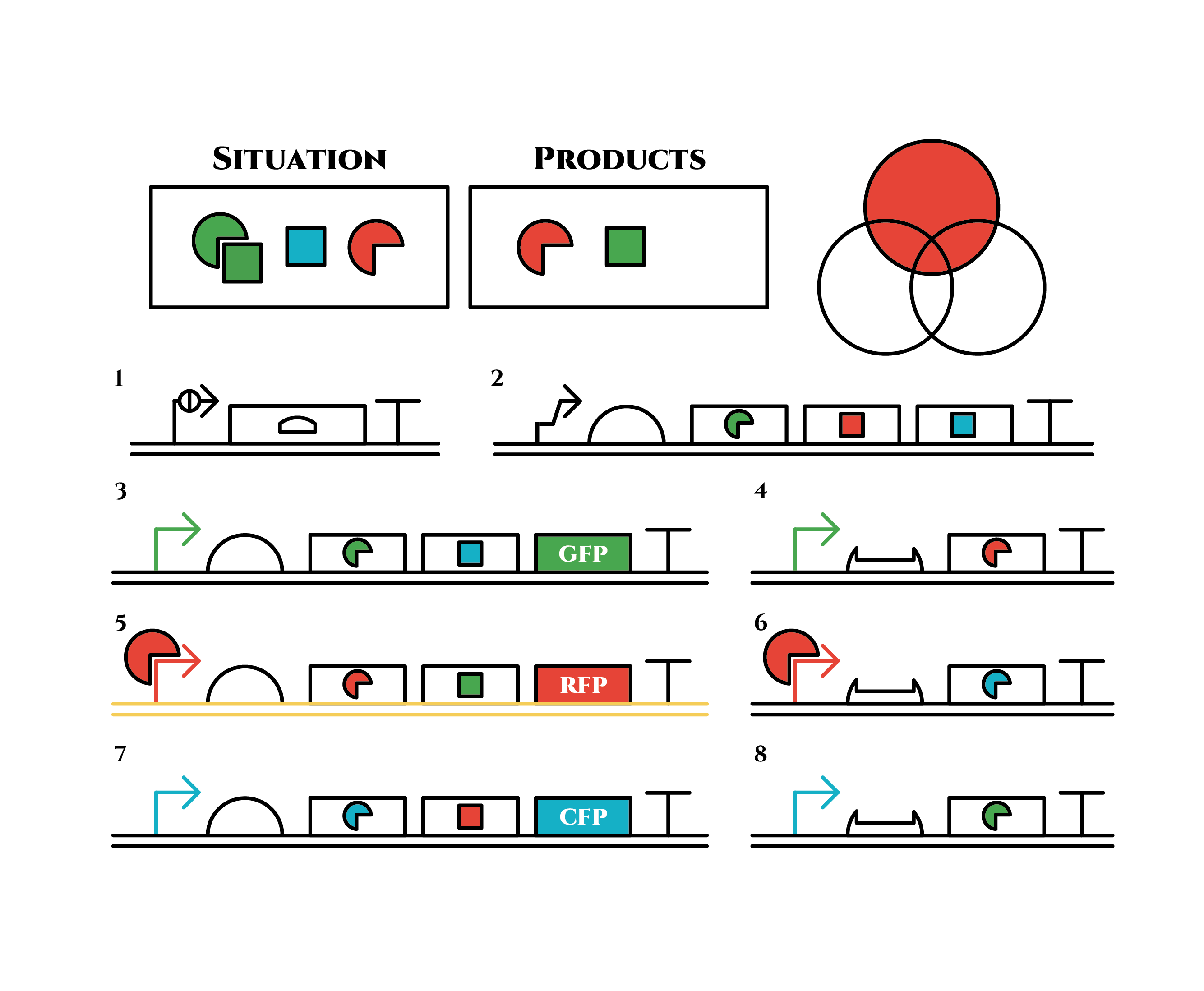
The constructions we want to make are explained below. The flame “SITUATION” indicates compounds such as RNAs and proteins that exist in the cell at a specific time are presented and the flame “PRODUCTS” shows products as the result of mRNA expressions. The upper right circles represents the fluorescent color the E. coli is emitting. The 8 genes below are our system to create multiple phenotypes over generations.
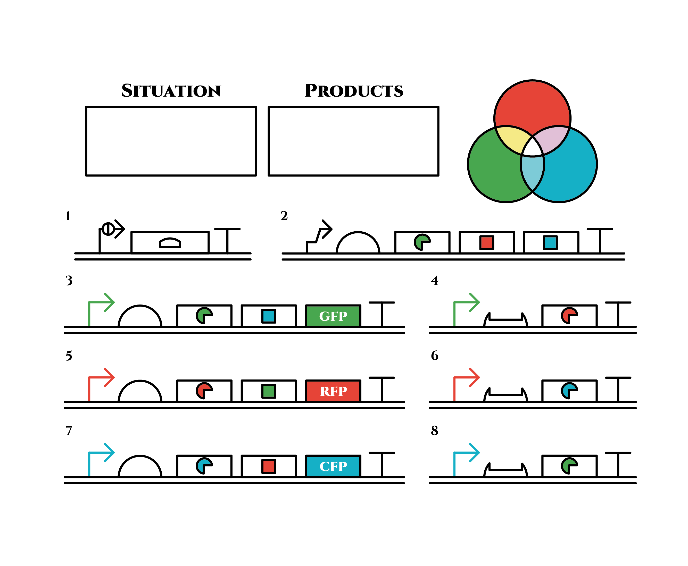
So, how these genes go?.
From the beginning, arabinose is added into the culture medium.
Arabinose induces the expression from mRNA of the gene 2. As a result, genes 3,4 are expressed under a positive feedback. Because of this positive feedback, the genes will be expressed stably without arabinose here on. The mRNAs transcribed from gene 3 are translated, while those from gene 4 are not because of the lack of trigger RNA.
Then, we remove arabinose from the culture.
At this time, despite of the degradation of the expressed factors at gene 2, new factors continue to be expressed from gene 3. Notice the cell is still not dividing at this point.
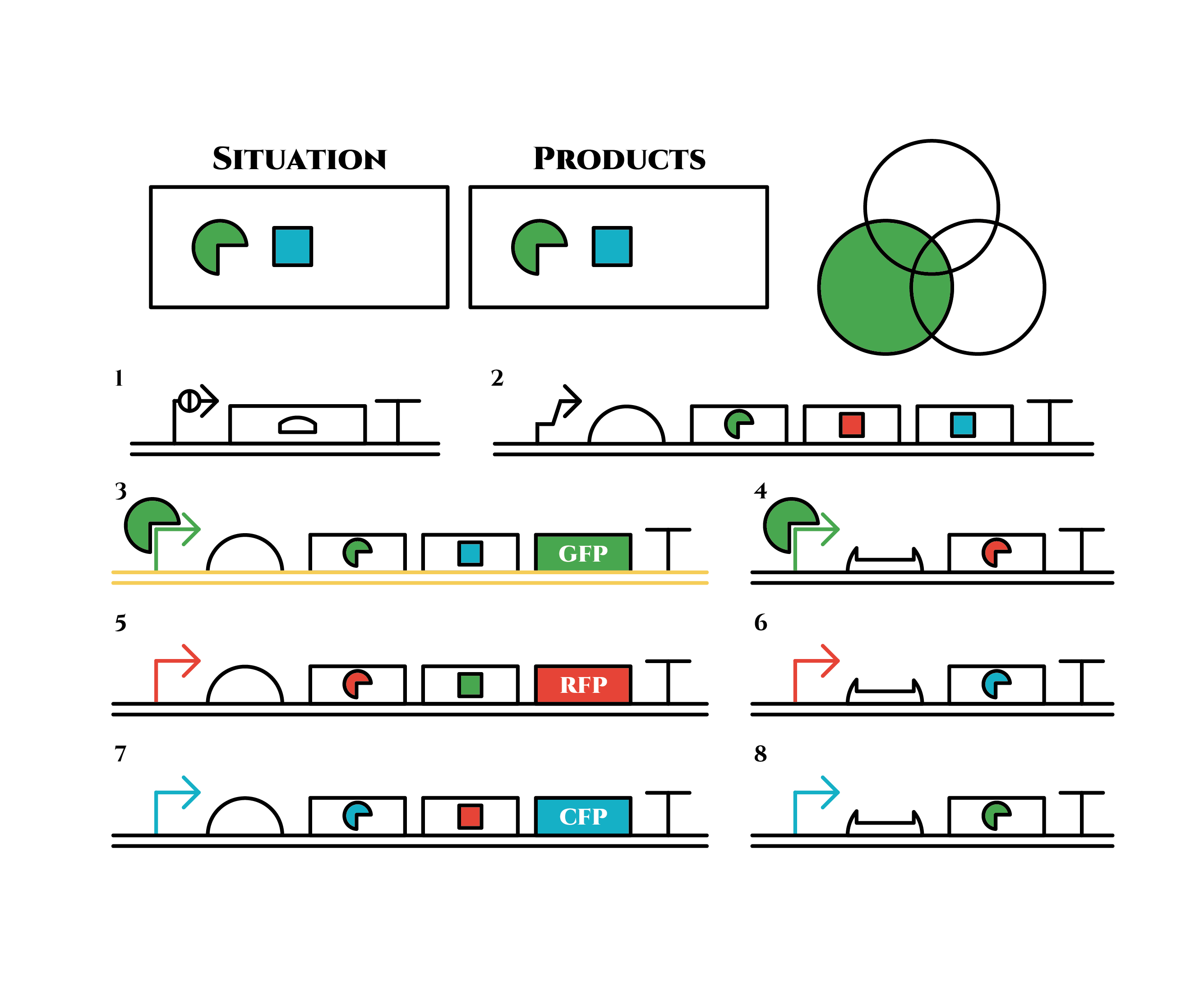 green sigma factors are made from gene 3, which in turn bind with the green sigma promoter and make more new green sigma factors. In this way, the gene promotes its own expression and this leads to the stable expression.
And what happens when cell division occurs?
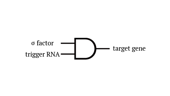
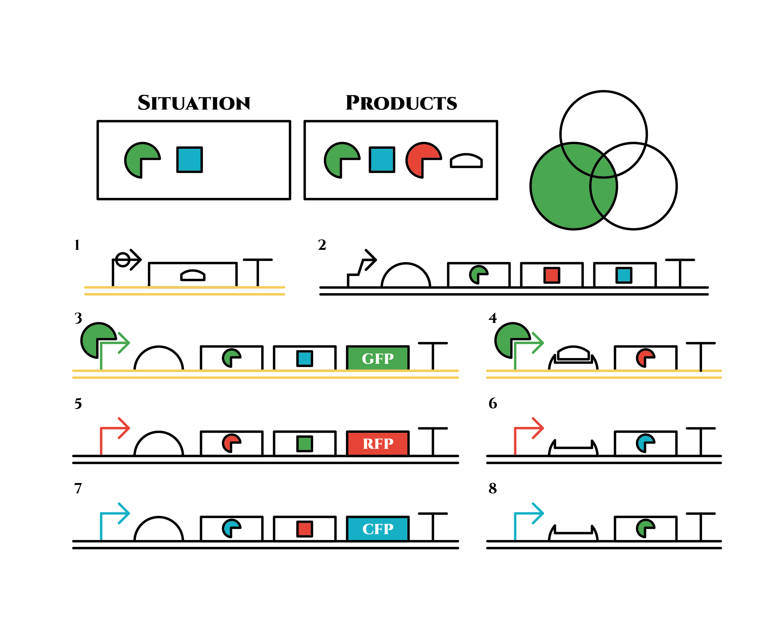 Gene 1 expresses and trigger RNAs are produced when cell division occurs. Then, let’s focus on gene 4. Genes downstream can only be expressed with both the existence of a green sigma factor and the trigger RNA, which seem like an AND gate,a kind of basic digital logic gates.
 Now we obtained a trigger RNA and a green sigma factor still remains, so the gene 4 finally begins to be expressed and red sigma factors are produced. Then the gene expression will change as below.
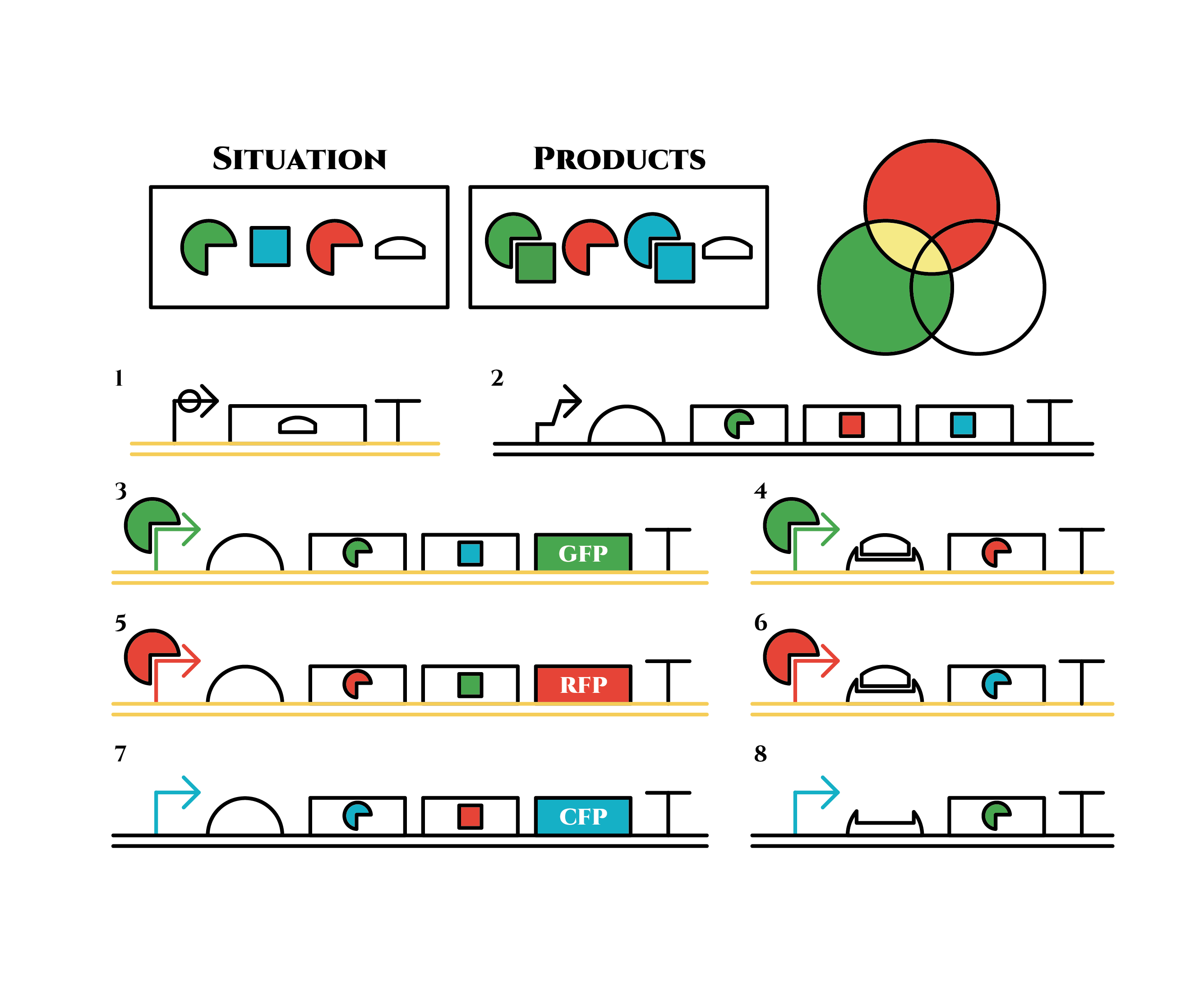 Under the existence of red sigma factors, genes 5,6 are expressed . Red sigma factors, green anti-sigma factors, blue sigma factors are made. While red sigma factors work on the red sigma promoter, newly-made blue sigma factors do not affect the blue sigma promoter because of its small number against the many blue anti-sigma factors that exist already. On the contrary, the small number of newly-made green anti-sigma factors cannot block the already-existing green sigma factors’ effect on the green sigma promoter completely.
Here is the state after cell division.
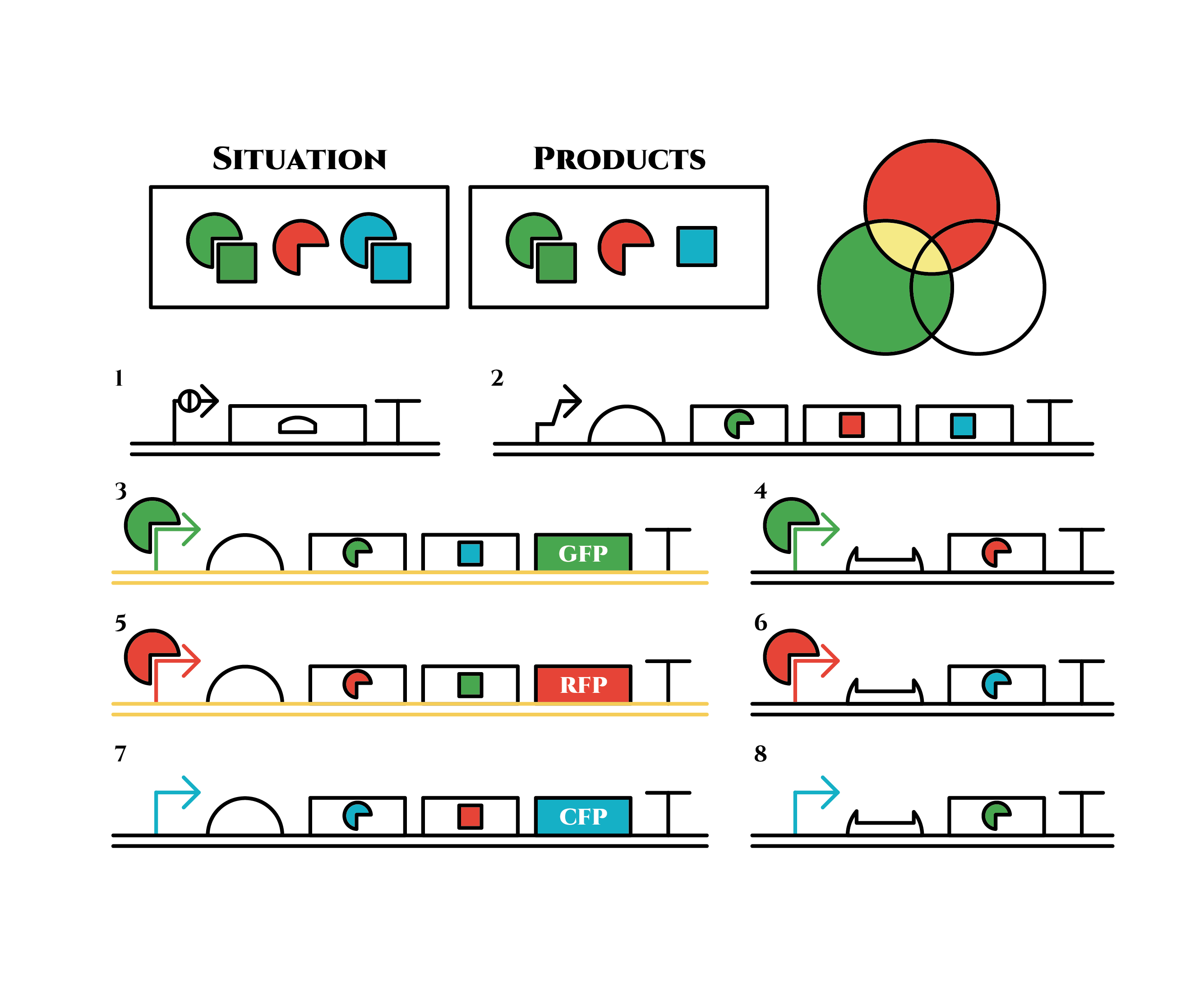 The genes on the right stop being translated. Plenty of red sigma factors and green anti-sigma factors are made from the gene 5. The expression of gene 3 gradually declines because of the increase of green anti-sigma factors.
When there are sufficient green anti-sigma factors, the gene expression will finally become as following.
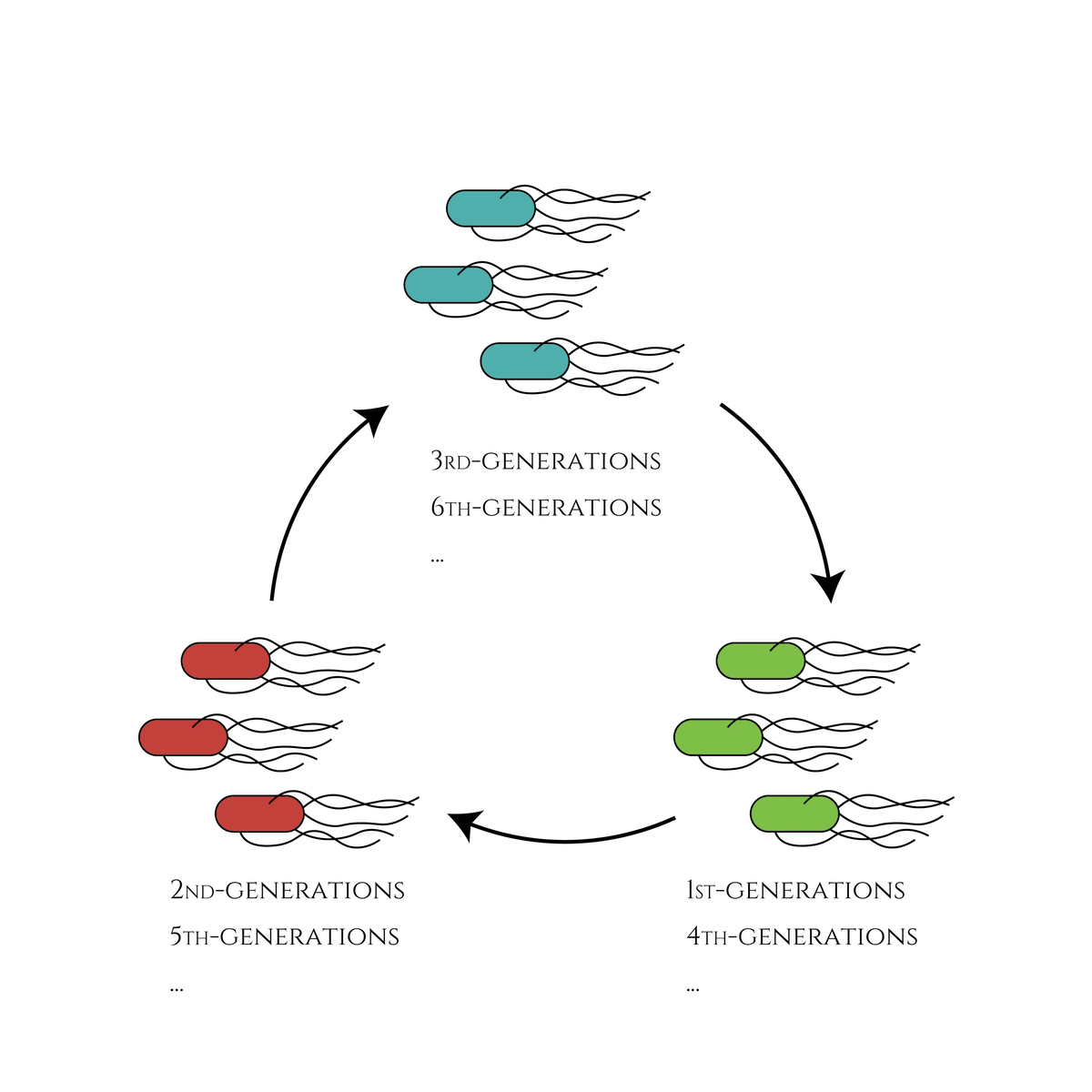
This is the exact same state as the phenotypic changes began, except that it is genes 5,6, instead of genes 3,4, that are being expressed. In other words, the expressed genes are switched through one cell division. The gene groups are symmetric in terms of colors (red, blue and green) when the reagent does not exist. Therefore, the expressing genes will be genes 7,8 after another division, and switch to genes 3,4 again after another. If the 3 patterns of gene expressions can be shifted in turn as expected, we can elongate the loop without a complicated gene design.
 Above is the gene groups that we designed. Toehold switch takes a key role of the gene expression change, and makes it easy to expand the system because it has a lot of pairs which do not crosstalk (link to application & citation). Also, it is a translational regulator, not transcriptional, so the response is expected to be faster.
Sigma factors and anti-sigma factors enables the pattern of the gene expression to be looped among cell divisions.
Pnrd switches the gene expression at the timing of a cell division.In reality, there are problems such as the inconsistency of the timing when Pnrd works and cell division, (Pnrd actually works on the time of DNA replication, not that of cell division.) and the preference of sigma factors to bind with anti-sigma factors than sigma promoters(see also model, and experiment pages). However, various phenotypes can be realized theoretically according to our computer simulation, depending on the properties of the factors and promoters.
References
[1] Figure 1 (B), Green, A. A., Silver, P. A., Collins, J. J., & Yin, P. (2014). Toehold switches: de-novo-designed regulators of gene expression. Cell, 159(4), 925-939.
[2]2014 iGEM UT-Tokyo wiki : https://2014.igem.org/Team:UT-Tokyo/Counter/Project?page=Project-block&contents=Project-2
Result
Cell Cycle Dependent Promoter: Pnrd
As described in the systems page, a cell division dependent promoter is essential for the functioning of our intergenerational phenotypic switching device. Stanford-Brown iGEM 2012 documented the characterisation of Promoter Pnrd ([http://parts.igem.org/Part:BBa_K847211 BBa_K847211])
and confirmed its functionality. However, since it was submitted in RFC[25] standard, the part was redesigned in RFC[10] to deal with the possible disadvantages of RFC[25] standard.
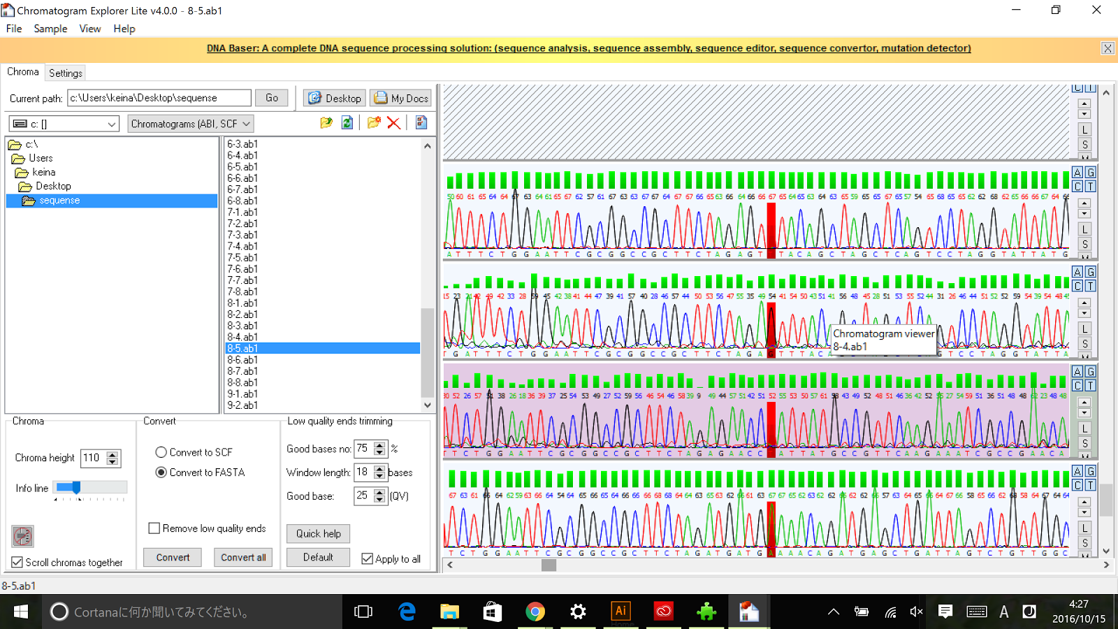
Sequencing results of Pnrd RFC[10]
The results of sequence show that the improved part contains the RFC[10] prefix and suffix.
Reconstructed in the RFC[10] format, the Pnrd promoter was ligated in front of part BBa_E0240 and compared to the standard promoter BBa_J23101. The measurement was made approximately 4h after 100 fold dilution in M9 in a 5 min interval. For details of our characterisation, refer to our protocol.
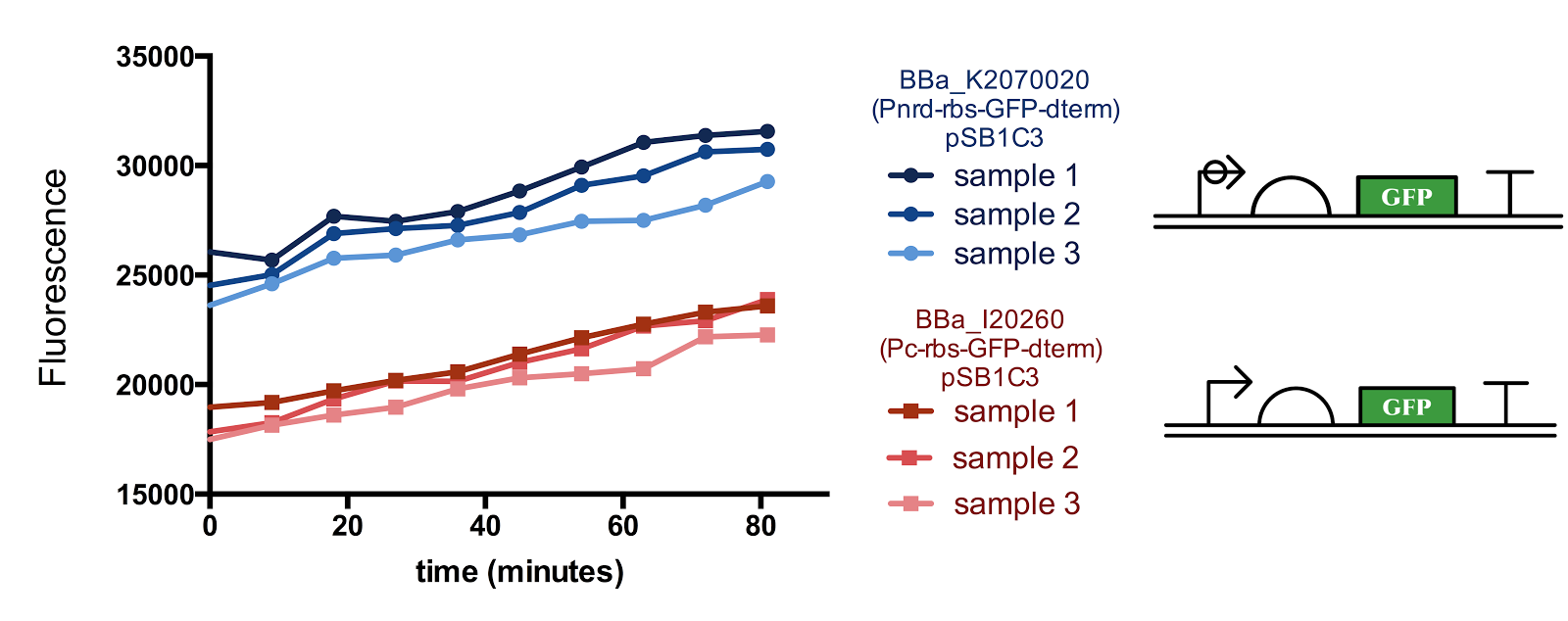
Figure 1. Measurement of nrd Promoter Activity.
The fluorescence from the Pnrd promoter is compared with that from the standard promoter BBa_J23101, 3 samples were measured every 9 minutes for each construct. Although there seems to be a slight sudden rise in the promoter activity from the 10-20th minute after the start of measurement, since the change in cell concentration could not be measured simultaneously with fluorescence, it is not certain whether the rise is influenced by the cell cycle/division.
SIGMA 35
In addition to the cell division dependent promoter, extracytoplasmic function (ECF) sigma factors are required in our device to coordinate between the cell division dependent promoter and Toehold Switch.
The figure below shows the result of our characterisation. Experiments were done according to methods described in our protocol.
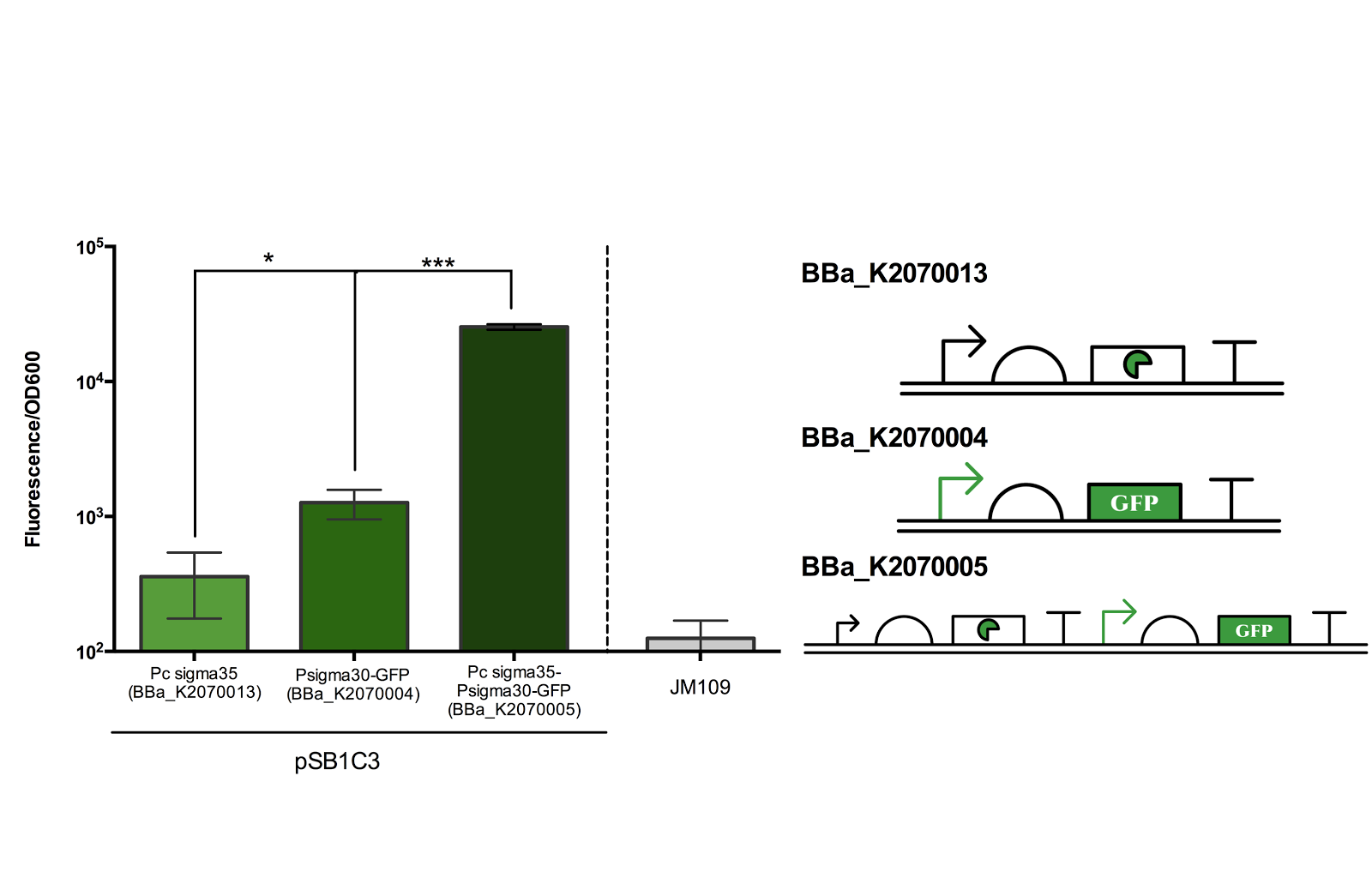
Figure 2. Measurement of ECF sigma35 and sigma30 promoter activity.
Fluorescence/OD600 of a construct containing both an ECF sigma35 generating device and ECF sigma 35 inducible GFP generating device BBa_K2070005 was compared to that containing only either one of the devices. *** for P> 0.001 indicates an extremely significant difference between the induced and uninduced state.
As can be seen from the above figure, the ECF sigma30 promoter is only activated in presence of ECF sigma35, suggesting that that the parts and devices constructed worked as expected. The ON state, measured in Fluorescence/OD600, was up to more than 10 fold of the OFF state. However, it should be noted that there is a leak in the promoter in its OFF state as indicated by the significance difference in Fluorescence/OD600 when compared to the construct expressing only sigma 35.
Once the functionality of the promoter and its cognate pair was confirmed, the part was ligated in pSB3K3 to measure its strength relative to the standard promoter BBa_J23101. The strength of the ECF30 promoter in its induced state was measured to be of RPU 3.2 units.
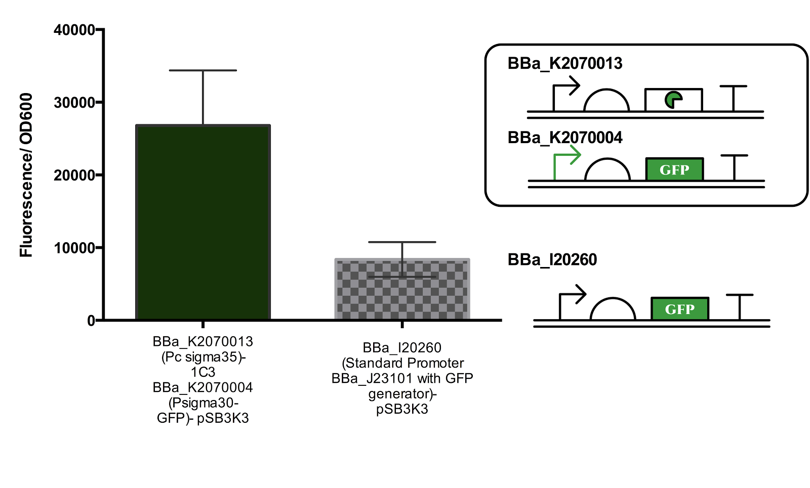
Figure 3. Measurement of Activated Sigma30 promoter Activity in comparison to Promoter BBa_J23101.
Both parts are ligated in plasmid pSB3K3. The part containing the constitutive sigma35 generator was double transformed into the cell for measurement. Data represents an average of 3 samples and error bars represent the standard deviation.
SIGMA 16
The second sigma factor that we have characterised and tested its functionality is ECF sigma16 from Pseudomonas entomophila.
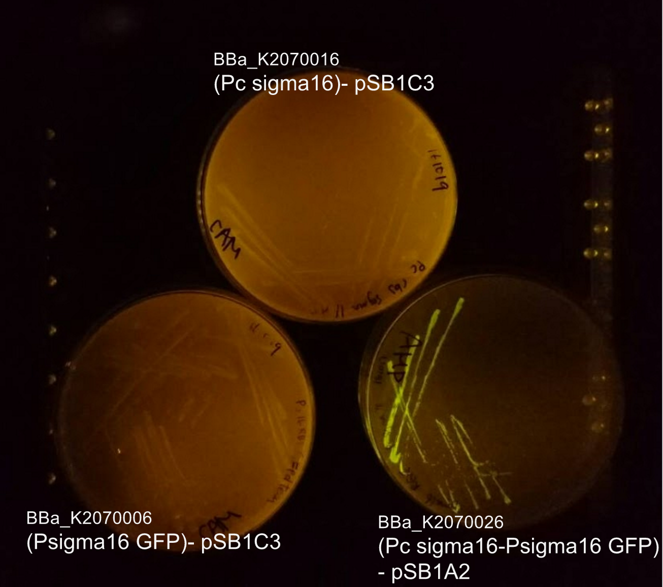
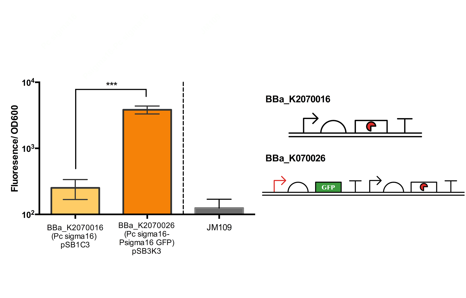
From bottom left: BBa_K2070006 (ECF sigma16 inducible GFP reporter), BBa_K2070026 (Constitutive ecf16 generator with ecf 16 inducible GFP reporter), BBa_K2070016 (Constitutive ECF sigma16 generator). As only cells with BBa_K2070026 is shown to fluorescence, it can be suggested that the devices works as expected.
Though we have checked its functionality on agar plate, due to time constraints, we were not able to measure the fluorescence of the Psigma16 GFP (BBa_using the spectrofluorophotometer.
Figure 5. Measurement of ECF sigma16 and Psigma16 GFP promoter activity.
Fluorescence/OD600 of a construct containing both an ECF sigma16 generating device and ECF sigma 16 inducible GFP and construct containing only the sigma 16 generator was measured. Measurement results indicate that there is a extremely significant difference between the two groups. Data taken from the average of 3 samples, with error bars indicating the standard deviation.
Though the fluorescence measurement results indicate that there is a extremely significant difference between the construct BBa_K2070016 and BBa_K2070026, since we were not able to compare the measurement with Psigma 16 GFP, we cannot be sure how much of the fluorescence is due to the activation of the sigma promoter and not the leak from the inducible promoter. Thus, further measurement is necessary to better confirm the activity of the ECF sigma16 and its cognate promoter.
SIGMA 11
ECF sigma 11 ([http://parts.igem.org/Part:BBa_K1461005 BBa_K1461005]) and its orthogonal sigma11 promoter([http://parts.igem.org/Part:BBa_K1461002 BBa_K1461002]) was characterised by Team UT-Tokyo in 2014. Since our system in design requires 3 ECF sigma factors and their corresponding promoter, in addition to the new sigma factors that we constructed, we decided to improve the characterisation of the existing the ECF sigma parts so that we can better understand their activity for the use in our system.
According to our modelling results, the concentration of sigma factors must be tuned so that while it must be high enough to activate the sigma promoter activity, it should not be too high that it cannot be repressed by anti sigma factors.
The approach that was taken in 2014 to tune the expression of ECF sigma factors was to tune the promoter that transcribes the genes coding for the ECF sigma factors. However, they reported that due to the possible leak from the PBAD promoter, the sigma expression could not be tuned appropriately.
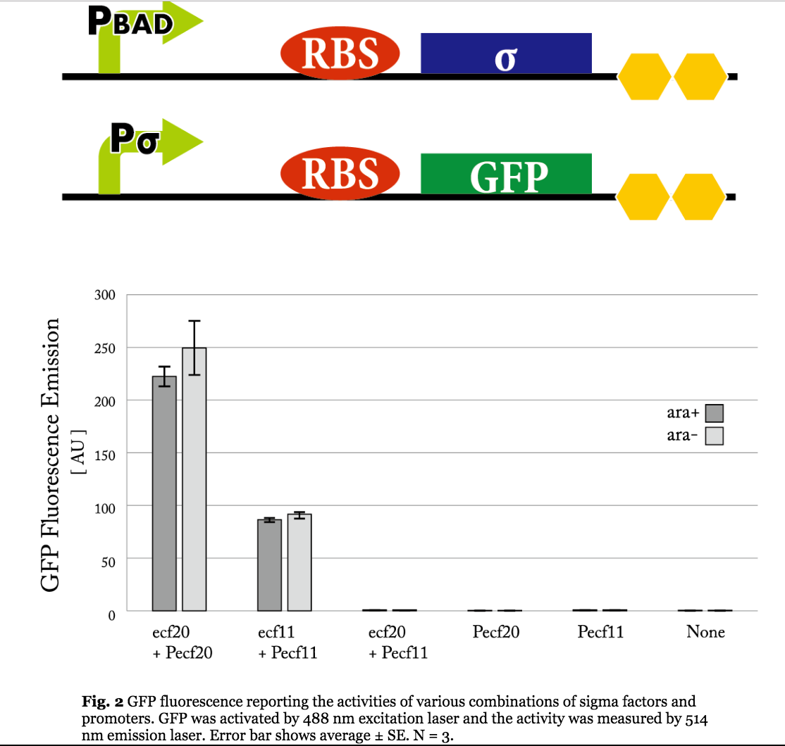
Figure 5. Previous iGEM results of sigma 11 activity. (Taken from UT-Tokyo 2014 wiki.)
Results indicate that though the ECF sigma11 factors were functional in activating the corresponding promoters, they were not able to influence the level of activation by tuning the expression level of promoter generating sigma factors.
We thus decided to test constitutive promoters of different strengths for generating the sigma factors and as well take another approach to tuning the induction of the sigma promoters, that is, by expressing the sigma factors on a plasmids of different copy number.
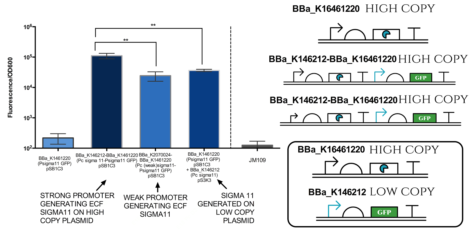
Figure 6. Measurement of sigma 11 promoter activity under different sigma11 generating conditions.
Strong promoter refers to BBa_J23101, while weak promoter refers to BBa_J23109. High copy plasmid refers to pSB1C3 (copy number of 100-300 per cell) and low copy plasmid refers to pSB3K3 (copy number of 10-12 per cell). Graph illustrates that there is a very significant difference( ** indicates P value 0.001 to 0.01) between different conditions. Data represents an average of 3 samples. Error bars show standard deviation.
The results above indicate that it is possible to tune the expression of the sigma 11 promoter by tuning levels of sigma11. The first approach is to change the expression level of promoter generating the sigma factors, and the second approach is to change the copy number of plasmid in which the sigma factors are expressed.
Anti Sigma Factors
To be used together with the ECF sigma11 and its promoter pair is anti sigma11 ([http://parts.igem.org/Part:BBa_K1461007 BBa_K1461007]) reported to be able to repress the activity of ECF sigma 11 in activating the sigma11 promoter. However, when its functionality was tested previously, by iGEM-UT Tokyo 2014, the results suggested that the anti sigma 11 was not able to repress the activity of ECF 11. It was hypothesised that anti sigma11 not functioning due to “ the sigma factors [were] expressed more than the anti-sigma factors could repress their activation of the corresponding promoters.” Thus, we attempted a new characterisation this time ligating anti 11 on a high copy plasmid and ECF sigma11 on a low copy plasmid in order to increase the level of anti 11 relative to sigma11.
The figures below show the result of our characterisation and the previous characterisation of anti 11 done by UT-Tokyo 2014.
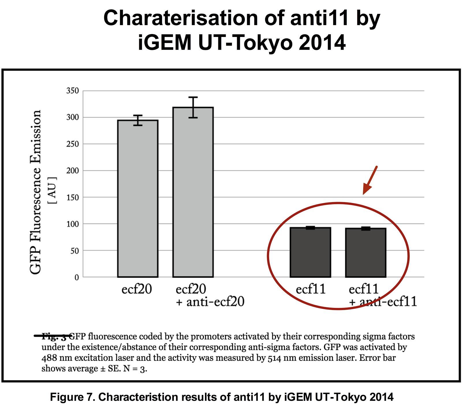
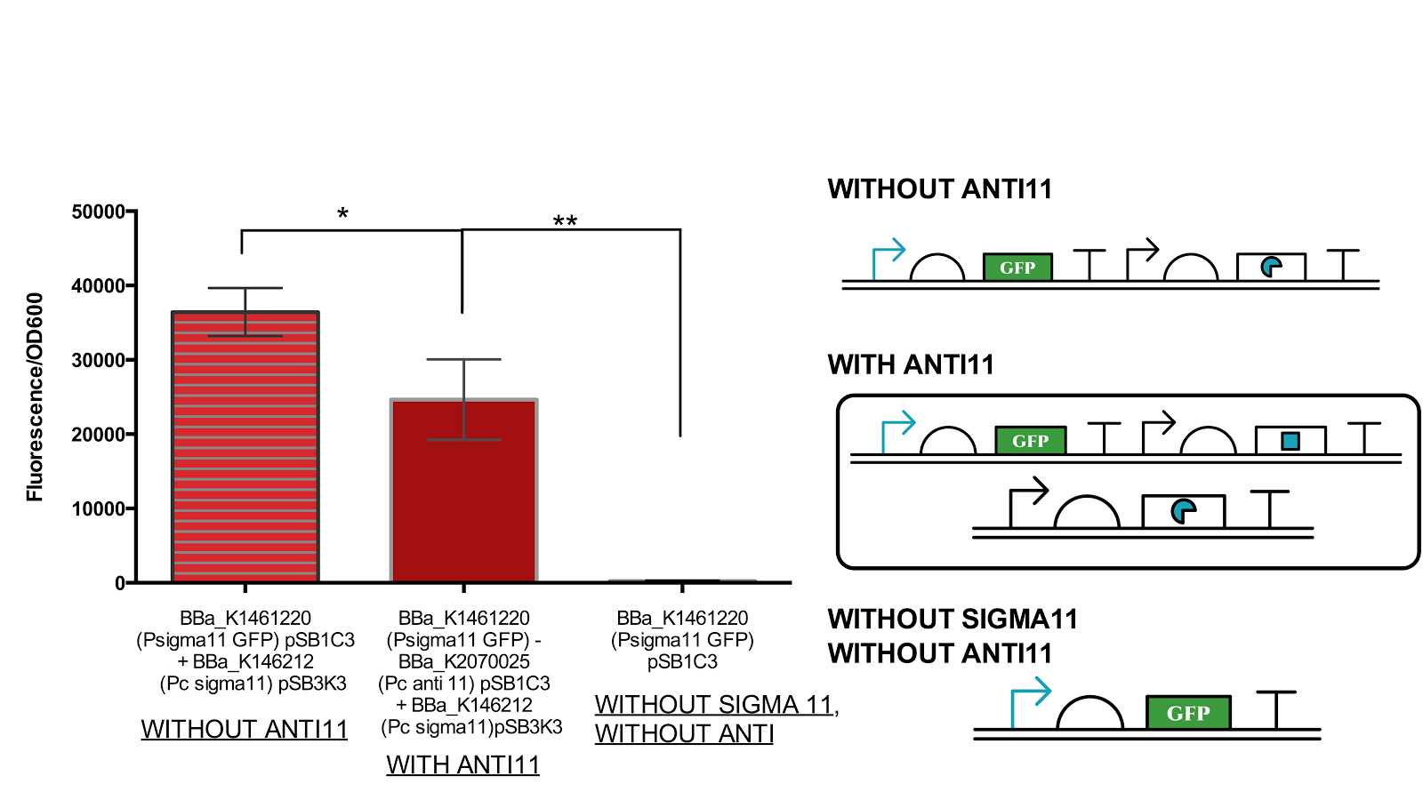
Figure 8. Functionality assay of anti 11 by increasing concentration of anti11 relative to sigma11.
Instead of generating sigma11 on backbone pSB1C3 as done in by iGEM UT-Tokyo 2014, sigma 11 was generated on backbone pSB3K3 and anti11 in pSB1C3 as an attempted to increase the level of anti11 relative to sigma11. The measurement shows that there is a significant level of difference between the anti sigma 11(-) construct and antisigma 11 (+). However, the difference between the complete OFF state (without sigma) and with anti 11 state is also very significant. Data represents an average of 3 samples with error bars representing the standard deviation.
From figure 6 above, it can be suggested that anti sigma11 can function to inhibit the activity of sigma11 as the fluorescence output from the sigma 11 promoter was significantly reduced in presence of anti11. Nevertheless, the anti sigma11 is not strong enough to function as a “switch” that can turn the promoter back to the state when there is no ECF sigma11 present.
D. The Rainbow
Completing the assay for the day, we obtained a beautiful piece of art on our screen.
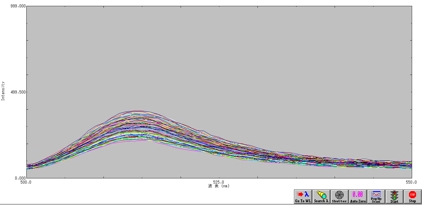
Figure 9. Niji.
The art piece is named Niji, meaning rainbow in Japanese. Each line of the Niji represents a step closer to the results that we obtained.
Application
In this section, we will explain three application examples;
- Developing solutions to contamination and pollution by using kill switch-inserted genetically modified microbes
- Improving the efficiency of cell division counting
- Application to the use of microbes in metabolic engineering
At first, we will explain the construction of a long cycle that would be used in these examples, afterwards explain these examples.
- Long cycle system
- Contents of Application
- Developing solutions to contamination and pollution by using kill switch-inserted genetically modified microbes
- Improving the efficiency of cell division counting
- Application to the use of microbes in metabolic engineering
The way to make a 100-stage cycle
In our project, sigma factors, promoters and anti-sigma factors all need three independent types to design a three-stage genetic cycle. So, if we want to create a 100-stage cycle, should we use 100 sets of transcriptional regulation components? The answer is NO.
Let's think about the creation of a 15-stage cycle which is much easier. You don't have to prepare 15 types of sigma factors to design this cycle; you need only nearly half -only 8 types! First of all, besides the three-stage cycle, you have to create a five-stage cycle with transcriptional regulation components which are not used in a three-stage cycle. By transferring these two cycles into E. coli at the same period, E. coli will obtain 15 different expression patterns. Furthermore, by constructing AND circuit that receives two transcription factors expressed in the last generation of each cycle as input, you can control what genes would be expressed in the 15th generation. In the same way, you can control genes that would be expressed in any other generations.
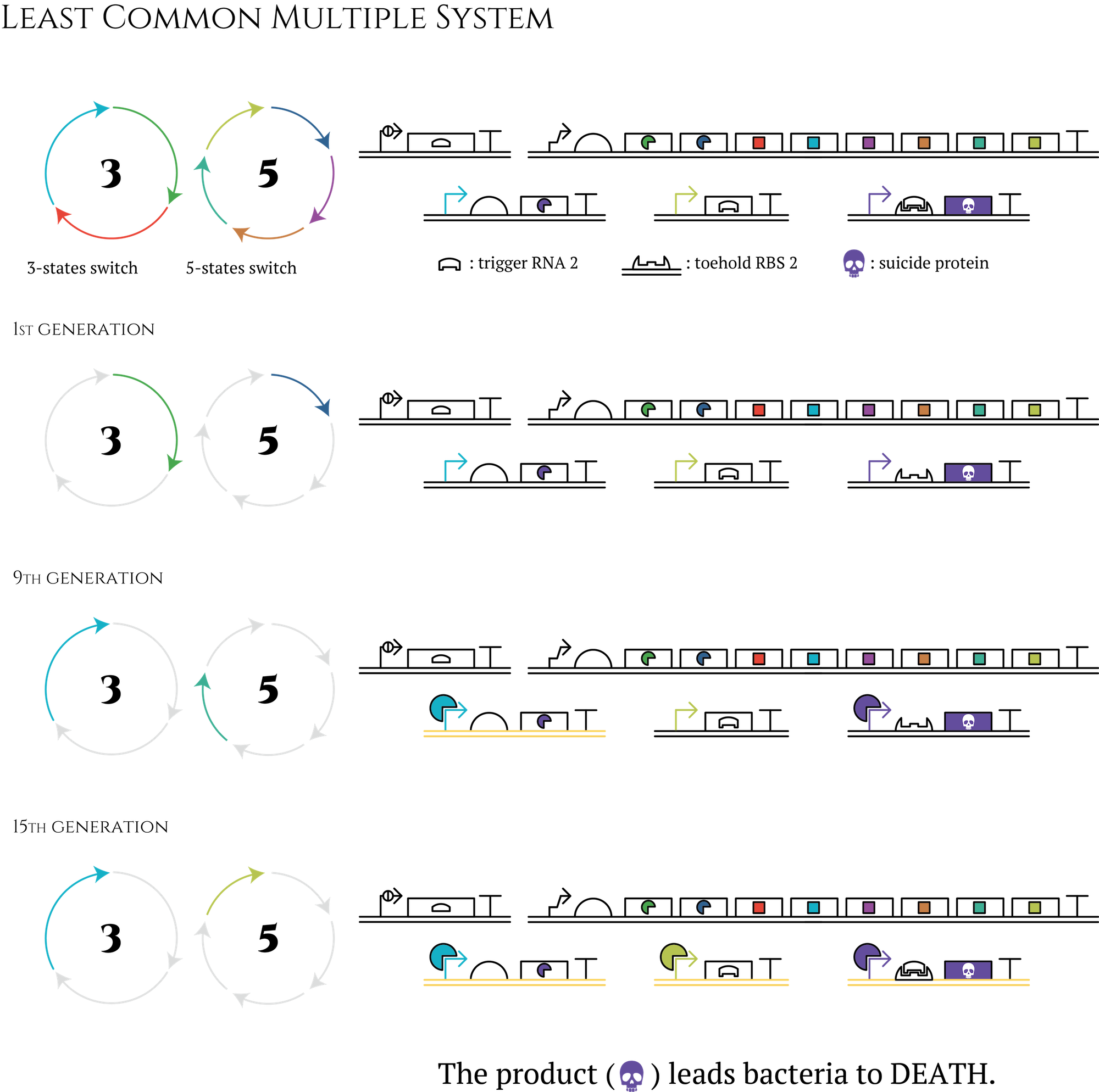
Figure. The circle in which the letter 3 is written is an abbreviation for gene 3 to gene 8 shown in “system” section. The circle in which the letter 5 is written is a counterpart of a 5-state system.
This method enables us to create even 105-stage genetic cycles by combining three-stage, five-stage and seven-stage cycles. Also the number of transcriptional regulation components we have to prepare is only 15. Even if you consider other components necessary to construct AND circuit, the total number of transcriptional regulation components could be far less than 100.
1. Developing solutions to contamination and pollution by using kill switch-inserted genetically modified microbes
It is true that these days environmental destructions are getting more serious issues, such as oil spill and soil contamination. It is quite difficult to clean up and collect causing non-biotic substances once released to the natural environment[1]. To deal with this problem, a number of solutions are proposed, and one way is the utilization of DNA modified microbes that can break down or detoxify contaminants in the environmental media[2]. To use genetically modified microbes might be able to realize the more efficient processing system than natural microbes. And from a viewpoint of preserving biodiversity, using genetically modified microbes, which will kill themselves, is better than using microbes of alien species when we decontaminate.
However, release of living modified organisms to the natural environment results in ecosystem destruction, particularly in genetic pollution, as it is prohibited by Cartagena Protocol.
Then, we propose the results of our project as a beneficial solution to this issue. Our designed system that expressed genes will change in each generation would make it possible to create microbes able to commit a suicide without external influence after a certain period of time. This can be realized with transferring genes that can remove contaminants to a former generation, and at the same time, inserting genes that can kill the cell itself(kill switch) in later generation[3]. Using this type of microbes, we can achieve the goal of contaminant removal and also reduce negative influence on the environment, due to the fact that the microbes would die over spontaneously after achieving the goal.
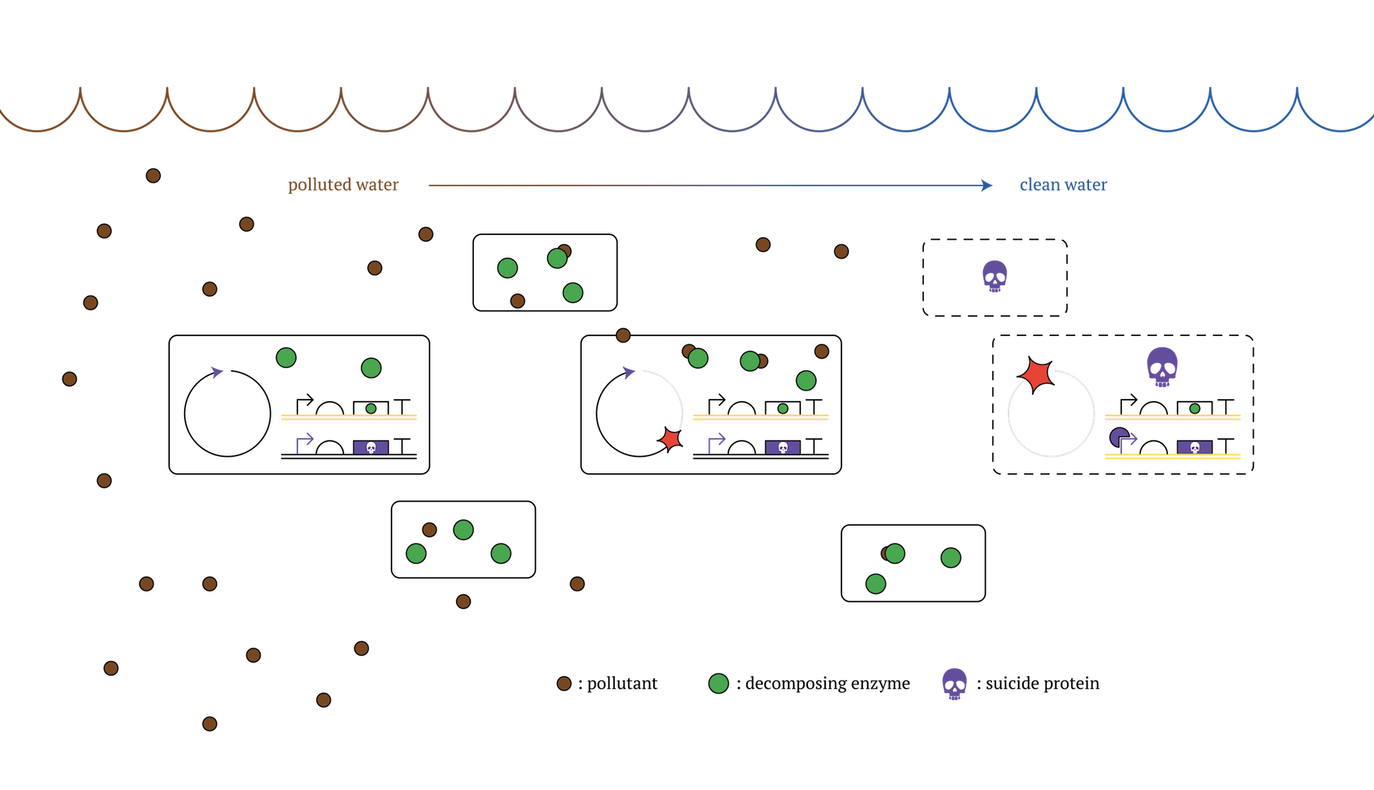
Figure. GM microorganisms which decontaminate polluted sea and die after a certain number of cell division [2]
We researched and discussed the vulnerability to release genetically modified microbes into natural environment and it is explained on Human Practices.
2. Improving the efficiency of cell division counting
In our project, we created the genetic cycle with three stages that the color of E. coli would change along with cell divisions. This system would be applied for a new cell division counting method that researchers can guess how many times the cells have divided just by observing the cell color, such as the 1st generation shows red, the 2nd generation shows green and so on. This method could be useful for counting cell divisions in embryonic development research.
Some conditions of Embryonic cleavage in Eukaryote are different from cell division of E. coli. For example, the promoter works in the cleavage is not Pnrd, the promoter we used in our project. However, Eukaryote also has a promoter working only once during a cell cycle. Therefore, we believe that, in Eukaryote, there could be some alternative substances to the substances we use(e.g. RNAi, Transcription Factor), and a similar genetic cycle we designed in E. coli can also work in Eukaryote[4].
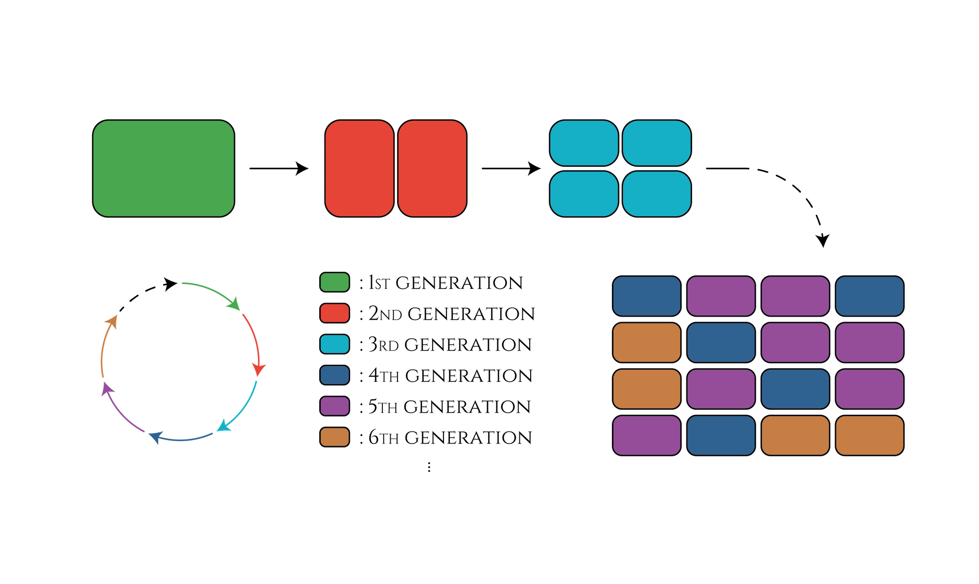
Figure. The cell division counter which show us how many times the cell have been divided by expressing different color of fluorescence proteins.
The past project that try to make division counting system by using Saccharomyces cerevisiae(https://2014.igem.org/Team:Gothenburg) This team intends to create a generation counter in Saccharomyces cerevisiae. The yeast cell would express fluorescent proteins of different colors according to the number of daughter cells spawn.
In the project of 2014 Gothenburg, the counter stops when cells are divided a certain number of times and, different types of SDS is needed for each generations. In our project, Cycle system is used and it allows counter not to stop counting. Moreover we don’t need different types of factors or promoters for each cell division. Therefore, our system is more useful for cell division counter.
3. Application to the use of microbes in metabolic engineering
Methods that improve the efficiency of industrially beneficial reactions by increasing the productivity of certain enzymes by using microbes are widely researched, developed and practiced. As our designed system enables E. coli itself to change the expression of genes periodically, this system could make such metabolic reactions more effective. Here is one example; In the case of a multi-stage enzyme reaction which involves enzymes cannot work with other enzymes and needs to take a moment during each reactions, our system is useful because one cell produces different enzymes at different reaction stage by using our system and the multi-stage reactions would proceed.
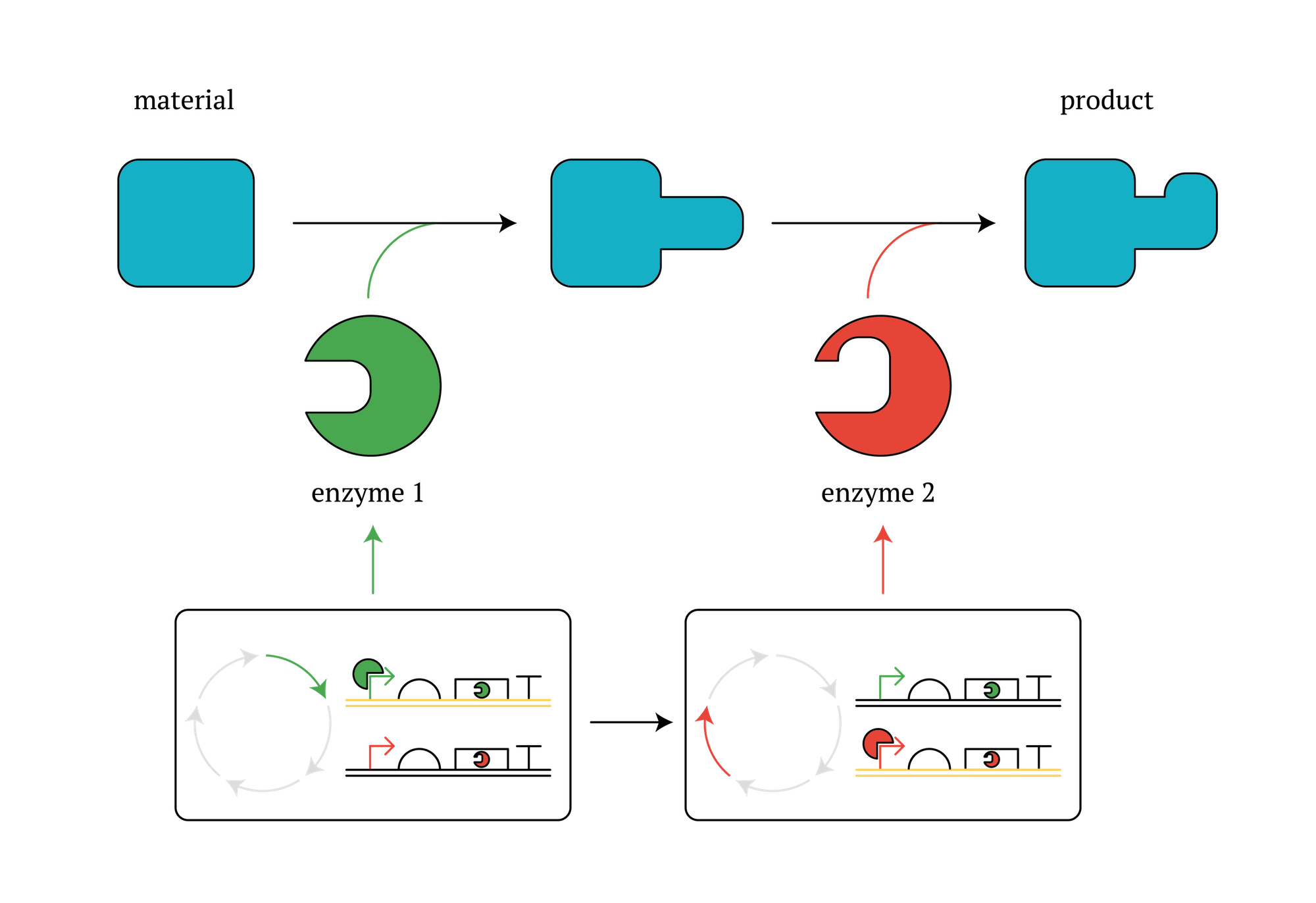
Figure. GM microorganisms which secure different enzymes in different stages in the cycle.
References
[1]Kingston, Paul F. "Long-term environmental impact of oil spills." Spill Science & Technology Bulletin 7.1 (2002).
[2]http://www.nature.com/nchembio/journal/v12/n2/full/nchembio.1979.html
[3]https://2014.igem.org/Team:Gothenburg

