m |
|||
| (8 intermediate revisions by 2 users not shown) | |||
| Line 17: | Line 17: | ||
*0 % - completely white paper pulp. | *0 % - completely white paper pulp. | ||
| + | |||
After the paper sheets were divided and mixed, they were washed with 1L of 60°C warm water and mixed with a kitchen blender for around two minutes. Afterwards, the pulp was filtrated through a sieve and the washed out paper fibers were dried in a 70 °C heater for one day. In the next step, the pulp was scooped out and once more mixed with the kitchen mixer for two minutes. With the end of this step, the pulp was ready for the deinking experiments. | After the paper sheets were divided and mixed, they were washed with 1L of 60°C warm water and mixed with a kitchen blender for around two minutes. Afterwards, the pulp was filtrated through a sieve and the washed out paper fibers were dried in a 70 °C heater for one day. In the next step, the pulp was scooped out and once more mixed with the kitchen mixer for two minutes. With the end of this step, the pulp was ready for the deinking experiments. | ||
| Line 24: | Line 25: | ||
The most commonly used industrial deinking method is called froth flotation. The principle behind this process is the separation of hydrophobic and hydrophilic particles in the pulp by a stream of air bubbles, after mechanical and chemical treatment of the paper pulp. In order to implement proper flotation-based deinking, a flotation cell is needed (figure 1). | The most commonly used industrial deinking method is called froth flotation. The principle behind this process is the separation of hydrophobic and hydrophilic particles in the pulp by a stream of air bubbles, after mechanical and chemical treatment of the paper pulp. In order to implement proper flotation-based deinking, a flotation cell is needed (figure 1). | ||
| − | {{UBonn_HBRS/image|url=//2016.igem.org/wiki/images/7/73/T--UBonn_HBRS--deinking_scheme.svg|alt=scheme|class= | + | <html> |
| + | <div class="clearfix"> | ||
| + | <div class="col-sm-offset-3 col-sm-6"> | ||
| + | </html> | ||
| + | {{UBonn_HBRS/image|url=//2016.igem.org/wiki/images/7/73/T--UBonn_HBRS--deinking_scheme.svg|alt=scheme|class=100|caption-class=with-caption|caption=<i>Figure 1. Flotation cell. The figure shows the basic mechanism of flotation cells used in industry. The pulp containing ink is added into water and a mixture of chemicals, including surfactants that form micelles after reaching a critical micelle concentration (CMC). The surfactant reduces surface tension and increases ink hydrophobicity. For this reason, ink is embedded within the micelles and rises to the top woth the airflow induced by an air pump. On the surface a foam is formed when surfactants react with alkaline chemicals (commonly NaOH). The foam with the ink is then collected into a seperate container and the remaining clean fibers are filtered and dried.</i>}} | ||
| + | <html></div></div></html> | ||
| + | |||
Chemicals that are used for the chemical treatment are: | Chemicals that are used for the chemical treatment are: | ||
| Line 32: | Line 39: | ||
*Na<sub>2</sub>SiO<sub>3</sub> (sodium silicate) – needed for pH adjustment, additive to use with hydrogen peroxide as it sequesters transition metal ions that decompose the peroxide. | *Na<sub>2</sub>SiO<sub>3</sub> (sodium silicate) – needed for pH adjustment, additive to use with hydrogen peroxide as it sequesters transition metal ions that decompose the peroxide. | ||
*C<sub>14</sub>H<sub>23</sub>N<sub>3</sub>O<sub>10</sub> (DTPA) – creates stable environment for hydrogen peroxide by inactivating metal ions. | *C<sub>14</sub>H<sub>23</sub>N<sub>3</sub>O<sub>10</sub> (DTPA) – creates stable environment for hydrogen peroxide by inactivating metal ions. | ||
| + | |||
| + | |||
| + | <html> | ||
| + | <div class="clearfix"> | ||
| + | <div class="col-sm-offset-3 col-sm-6"> | ||
| + | </html> | ||
| + | {{UBonn_HBRS/image|url=//2016.igem.org/wiki/images/6/6f/T--UBonn_HBRS--deinking_bubbles.svg|alt=bubbles|class=100|caption-class=with-caption|caption=<i>Figure 2. Surfactants (surface active agents) are substances containing both, hydrophilic and hydrophobic parts. They have three important roles in flotation deinking: 1) ink separation from fibers and prevention of redeposition; 2) agglomeration of smaller ink particles to bigger ones and increase in their hydrophobicity; 3) saponification reaction with NaOH leads to foam forming. Air bubbles connect to ink particles after their hydrophobicity is increased and leads to their rise to the surface.</i>}} | ||
| + | <html></div></div></html> | ||
| + | |||
Additionally, to the chemicals listed, a Ca2+ source can be added to the solution. However, the Ca2+ can also originate from hard water or from paper itself. | Additionally, to the chemicals listed, a Ca2+ source can be added to the solution. However, the Ca2+ can also originate from hard water or from paper itself. | ||
Another factor that has impact on deinking efficiency is the pH. It was shown that deinking in more alkaline environment yields in faster agglomeration of ink particles and assists in saponification reaction, thus increasing the efficiency of froth flotation. For this reason, the optimal pH value for flotation deinking is in a range between 8 and 10. | Another factor that has impact on deinking efficiency is the pH. It was shown that deinking in more alkaline environment yields in faster agglomeration of ink particles and assists in saponification reaction, thus increasing the efficiency of froth flotation. For this reason, the optimal pH value for flotation deinking is in a range between 8 and 10. | ||
| + | |||
==Enzymatic deinking== | ==Enzymatic deinking== | ||
| Line 45: | Line 62: | ||
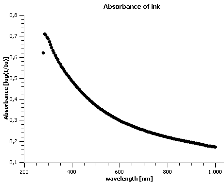
Before starting the experiments, the absorbance of our inkjet ink was determined in to determine the values that should be expected in further analysis (figure 3). | Before starting the experiments, the absorbance of our inkjet ink was determined in to determine the values that should be expected in further analysis (figure 3). | ||
| − | {{UBonn_HBRS/image|url=//2016.igem.org/wiki/images/1/18/T--UBonn_HBRS--deinking_absorbance_ink.png|alt=absorbance ink|class= | + | |
| + | <html> | ||
| + | <div class="clearfix"> | ||
| + | <div class="col-sm-offset-3 col-sm-6"> | ||
| + | </html> | ||
| + | {{UBonn_HBRS/image|url=//2016.igem.org/wiki/images/1/18/T--UBonn_HBRS--deinking_absorbance_ink.png|alt=absorbance ink|class=100|caption-class=with-caption|caption=<i>Figure 3. Inkjet ink absorbance spectrum. Inkjet ink was diluted 1:2 in order to determine the absorbance of ink particles.</i>}} | ||
| + | <html></div></div></html> | ||
==Filtration based deinking== | ==Filtration based deinking== | ||
| − | {{UBonn_HBRS/image|url=//2016.igem.org/wiki/images/0/0b/T--UBonn_HBRS--deinking_construction_1.jpg|alt=absorbance ink|class= | + | <html> |
| − | + | <div class="clearfix"> | |
| + | <div class="col-sm-offset-3 col-sm-6"> | ||
| + | </html> | ||
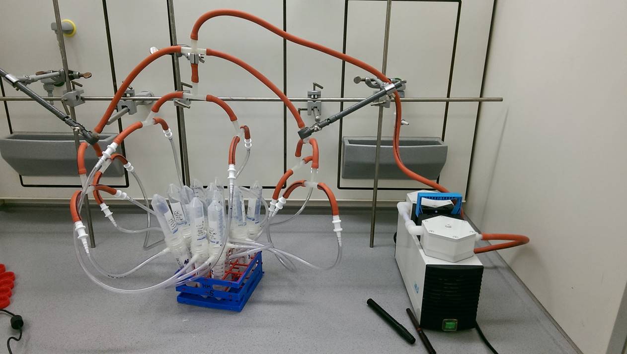
| + | {{UBonn_HBRS/image|url=//2016.igem.org/wiki/images/0/0b/T--UBonn_HBRS--deinking_construction_1.jpg|alt=absorbance ink|class=100|caption-class=with-caption|caption=<i>Figure 4. Filtration-based deinking system. The experimental setup is made out of 50 mL falcons, 100 µm sterilflips from Merck milipore, connective pipes and vacuum pump.</i>}} | ||
| + | <html></div></div></html> | ||
| + | |||
| + | |||
To keep the scale of the experiments manageable, 50 mL falcons were chosen as containers for the small scale deinking. | To keep the scale of the experiments manageable, 50 mL falcons were chosen as containers for the small scale deinking. | ||
Firstly, the standard chemicals and water are pipetted into the falcons according to the *protocol*, afterwards pulp is added and the mixture is vortexed until it becomes slurry. Later, the falcons are incubated in a 50 °C water bath for 30 min. Although the falcons should have been shaken during the incubation time, this was not possible in our lab. After incubation, the slurry is vortexed again and the falcons are connected to the deinking apparatus as shown in figure 4. When vacuum filtration is finished, paper fibers, which stay on the filters are left to dry for one day and the flow-through is analysed further. | Firstly, the standard chemicals and water are pipetted into the falcons according to the *protocol*, afterwards pulp is added and the mixture is vortexed until it becomes slurry. Later, the falcons are incubated in a 50 °C water bath for 30 min. Although the falcons should have been shaken during the incubation time, this was not possible in our lab. After incubation, the slurry is vortexed again and the falcons are connected to the deinking apparatus as shown in figure 4. When vacuum filtration is finished, paper fibers, which stay on the filters are left to dry for one day and the flow-through is analysed further. | ||
| Line 59: | Line 88: | ||
After the flow-through is produced, it is once again vortexed and 100 μm of the samples together with water as a blank are transferred into 96 well plates in order to measure the absorbance of it with the plate reader (in our laboratory, the Tecan Infinite 200 PRO multimode reader was used). The plate reader works as spectrophotometer, it compares the light intensity of the emitted light to the light intensity of the light detected after a passage through the sample. | After the flow-through is produced, it is once again vortexed and 100 μm of the samples together with water as a blank are transferred into 96 well plates in order to measure the absorbance of it with the plate reader (in our laboratory, the Tecan Infinite 200 PRO multimode reader was used). The plate reader works as spectrophotometer, it compares the light intensity of the emitted light to the light intensity of the light detected after a passage through the sample. | ||
| − | {{UBonn_HBRS/image|url=//2016.igem.org/wiki/images/1/16/T--UBonn_HBRS--deinking_absorbance_980.png|alt=absorbance ink 980|class= | + | |
| + | <html> | ||
| + | <div class="clearfix"> | ||
| + | <div class="col-sm-offset-3 col-sm-6"> | ||
| + | </html> | ||
| + | {{UBonn_HBRS/image|url=//2016.igem.org/wiki/images/1/16/T--UBonn_HBRS--deinking_absorbance_980.png|alt=absorbance ink 980|class=100|caption-class=with-caption|caption=<i>Figure 5. Absorbance of inkjet ink at 980 nm. The graph shows the absorbance values of different treatment conditions: water, standard chemical, oleic acid and oleic acid + citrate buffer, at 980 nm wavelength. The higher the absorbance at these wavelengths, the better deinking worked and the more ink has been removed. Graphs are decreasing and linear as expected and indicate that standard chemical deinking has the highest efficiency while the oleic acid and citrate buffer mixture the lowest. However, when subtracted 0 % absorbance from other absorbance, in order to reject the fiber still present in flow-through, it can be seen that the values are almost the same, thus meaning that the procedure/analysis might be incorrect.</i>}} | ||
| + | <html></div></div></html> | ||
| Line 65: | Line 100: | ||
The significant precondition for accurate results when measuring absorbance is a particle-free solution. However, some paper fibers pass the filter membranes and are present in the flow-through. These residual fibers might lead to inaccurate and unstable values. For this reason, it was tried to dissolve ink by using solvents with different polarity (table 1). | The significant precondition for accurate results when measuring absorbance is a particle-free solution. However, some paper fibers pass the filter membranes and are present in the flow-through. These residual fibers might lead to inaccurate and unstable values. For this reason, it was tried to dissolve ink by using solvents with different polarity (table 1). | ||
| + | |||
| + | |||
| + | {{UBonn_HBRS/table-start|class=with-caption}} | ||
| + | <html> | ||
| + | <thead> | ||
| + | <tr> | ||
| + | <th>Solvent</th> | ||
| + | <th>Volume[µL]</th> | ||
| + | <th>relative polarity</th> | ||
| + | </tr> | ||
| + | </thead> | ||
| + | <tbody> | ||
| + | <tr> | ||
| + | <td><strong>Acetone</strong></td> | ||
| + | <td>10</td> | ||
| + | <td>0.355</td> | ||
| + | </tr> | ||
| + | <tr> | ||
| + | <td><strong>Isopropanol</strong></td> | ||
| + | <td>10</td> | ||
| + | <td>0.546</td> | ||
| + | </tr> | ||
| + | <tr> | ||
| + | <td><strong>Ethanol</strong></td> | ||
| + | <td>10</td> | ||
| + | <td>0.654</td> | ||
| + | </tr> | ||
| + | </tbody> | ||
| + | </html> | ||
| + | {{UBonn_HBRS/table-end}} | ||
| + | <html><div class="caption"></html> | ||
| + | <strong>Table 1. Comparison of different solvents. Different concentrations of various solvents were used in order to figure out which one has the ability to dissolve ink thus separating it from fibers in flow-through. However, the experiments were not successful as only the ink that is the most strongly fused to fibers is present at the end of deinking process.</strong> | ||
| + | <html></div></html> | ||
| + | |||
==Rotary evaporator== | ==Rotary evaporator== | ||
After being unable to separate ink from fibers present in flow through, it was decided to try to concentrate ink present there. For this purpose a rotary evaporator was used. The flow through solution was transferred into the apparatus in order to evaporate the water from the mixture. Afterwards, the fibers could be spun down with a centrifuge and the resulting concentrated ink solution could be taken for the absorbance scan. However, the more water was evaporated, the more ink particles strongly fused to the glass vessel’s surface and only the fibers were left. It was tried to dissolve the ink from the walls of the vessel, but we were unable to achieve this. | After being unable to separate ink from fibers present in flow through, it was decided to try to concentrate ink present there. For this purpose a rotary evaporator was used. The flow through solution was transferred into the apparatus in order to evaporate the water from the mixture. Afterwards, the fibers could be spun down with a centrifuge and the resulting concentrated ink solution could be taken for the absorbance scan. However, the more water was evaporated, the more ink particles strongly fused to the glass vessel’s surface and only the fibers were left. It was tried to dissolve the ink from the walls of the vessel, but we were unable to achieve this. | ||
| + | |||
==Grayscale== | ==Grayscale== | ||
| Line 74: | Line 144: | ||
Both sides of the resulting dry paper disks were scanned in 5 different places on an office scanner. Afterwards, the images were analysed and the grayscale value obtained with the program ImageJ (figure 6). | Both sides of the resulting dry paper disks were scanned in 5 different places on an office scanner. Afterwards, the images were analysed and the grayscale value obtained with the program ImageJ (figure 6). | ||
| − | |||
| + | <html> | ||
| + | <div class="clearfix"> | ||
| + | <div class="col-sm-offset-3 col-sm-6"> | ||
| + | </html> | ||
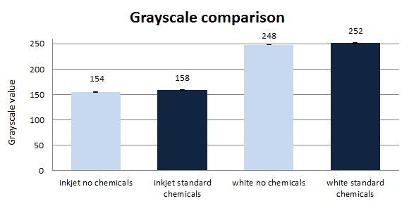
| + | {{UBonn_HBRS/image|url=//2016.igem.org/wiki/images/4/4c/T--UBonn_HBRS--deinking_grayscale_comparis.png|alt=grayscale|class=100|caption-class=with-caption|caption=<i>Figure 6. Comparison of grayscale. The diagram shows how the brightness of paper increases when treating pulp with water only and with standard chemicals. Inkjet pulp‘s brightness increases by 4 units (2.6%) and white paper brightness increases by 6 units (2.4%). </i>}} | ||
| + | <html></div></div></html> | ||
| Line 81: | Line 156: | ||
In order to improve the deinking mechanism in our laboratory, the experiments were up-scaled. The apparatus and process itself now were much more similar to the ones used in industry (figure 7). | In order to improve the deinking mechanism in our laboratory, the experiments were up-scaled. The apparatus and process itself now were much more similar to the ones used in industry (figure 7). | ||
| − | {{UBonn_HBRS/image|url=//2016.igem.org/wiki/images/f/fe/T--UBonn_HBRS--deinking_construction_2.jpg|alt=construction two|class= | + | |
| + | <html> | ||
| + | <div class="clearfix"> | ||
| + | <div class="col-sm-offset-3 col-sm-6"> | ||
| + | </html> | ||
| + | {{UBonn_HBRS/image|url=//2016.igem.org/wiki/images/f/fe/T--UBonn_HBRS--deinking_construction_2.jpg|alt=construction two|class=100|caption-class=with-caption|caption=<i>Figure 7. Flotation-based deinking setup. The apparatus partially imitates froth flotation deinking used in industry. It consists out of a beaker that is used as a container for deinking, a stirrer and its engine, an air pump and a thermometer. During the chemical deinking, foam grows out of the beaker and can be collected.</i>}} | ||
| + | <html></div></div></html> | ||
| + | |||
Chemical deinking was carried out using this experimental setup. Chemicals and 50 °C water were added to the beaker together with the pulp. The stirring was constant in order to mix the chemicals and fibers together. After the start of the air pump, foam, collecting ink, starts to form. | Chemical deinking was carried out using this experimental setup. Chemicals and 50 °C water were added to the beaker together with the pulp. The stirring was constant in order to mix the chemicals and fibers together. After the start of the air pump, foam, collecting ink, starts to form. | ||
After the collection of approximately 1 L of foam, its pH was measured. The result was near 10. Later on, froth was defoamed with acetone so that the absorbance measurements could be carried out. Even though some fibers are always present in foam, it is known that under proper conditions it is possible to reject their loss. However, after defoaming it was observed that froth contains much more fibers than it was expected. Due to the slurry appearance, absorbance could not be measured properly | After the collection of approximately 1 L of foam, its pH was measured. The result was near 10. Later on, froth was defoamed with acetone so that the absorbance measurements could be carried out. Even though some fibers are always present in foam, it is known that under proper conditions it is possible to reject their loss. However, after defoaming it was observed that froth contains much more fibers than it was expected. Due to the slurry appearance, absorbance could not be measured properly | ||
| + | |||
==Ink removal== | ==Ink removal== | ||
| Line 90: | Line 173: | ||
| − | {{UBonn_HBRS/image|url=//2016.igem.org/wiki/images/9/96/T--UBonn_HBRS--deinking_black_things.jpg|alt=black things|class= | + | <html> |
| + | <div class="clearfix"> | ||
| + | <div class="col-sm-offset-3 col-sm-6"> | ||
| + | </html> | ||
| + | {{UBonn_HBRS/image|url=//2016.igem.org/wiki/images/9/96/T--UBonn_HBRS--deinking_black_things.jpg|alt=black things|class=1050|caption-class=with-caption|caption=<i>Figure 8. Ink removed. The black spot on the surface is the ink separated from fibers by addition of CaCl2</i>}} | ||
| + | <html></div></div></html> | ||
| Line 98: | Line 186: | ||
| − | {{UBonn_HBRS/image|url=//2016.igem.org/wiki/images/a/ab/T--UBonn_HBRS--deinking_water_vs_std.png|alt=water vs standard|class= | + | <html> |
| + | <div class="clearfix"> | ||
| + | <div class="col-sm-offset-3 col-sm-6"> | ||
| + | </html> | ||
| + | {{UBonn_HBRS/image|url=//2016.igem.org/wiki/images/a/ab/T--UBonn_HBRS--deinking_water_vs_std.png|alt=water vs standard|class=100|caption-class=with-caption|caption=<i>Figure 9. Water treatment versus standard chemical treatment. The diagram indicates the change in the value at 700 nm both in 50 and 100 % pulps. The value of 50 % paper fibers increases by around 7.6 units while 100% - by 6.5 units. </i>}} | ||
| + | <html></div></div></html> | ||
| + | |||
The data from figure 9 proves that the deinking and its analysis system in laboratory scale was established. For this reason, tests of citrate buffer and one of the enzyme, Xylanase, were started. However, all the experiments resulted in visually much darker paper even when compared to simply washed paper pulp (figure 10). | The data from figure 9 proves that the deinking and its analysis system in laboratory scale was established. For this reason, tests of citrate buffer and one of the enzyme, Xylanase, were started. However, all the experiments resulted in visually much darker paper even when compared to simply washed paper pulp (figure 10). | ||
| − | {{UBonn_HBRS/image|url=//2016.igem.org/wiki/images/ | + | <html><div class="clearfix"></html> |
| + | {{UBonn_HBRS/image|url=//2016.igem.org/wiki/images/6/6a/T--UBonn_HBRS--deinking_last_scan.jpg|alt=water vs standard|class=100|caption-class=with-caption|caption=<i>Figure 10. Visual differences between different conditions. In the picture it can be clearly seen that after treatment, pulp (from top to the bottom: 100%, 50%, 25%) with citrate buffer and enzyme stay even darker than the ones washed out only with water.</i>}} | ||
| + | <html></div></html> | ||
| + | |||
Another problem is citrate buffer‘s crystallization. After the pulp treated with citrate buffer is dry, it tends to show higher values when scanning at 700 nm. This is caused by the crystals of citrate buffer and leads to misinterpreting of results. | Another problem is citrate buffer‘s crystallization. After the pulp treated with citrate buffer is dry, it tends to show higher values when scanning at 700 nm. This is caused by the crystals of citrate buffer and leads to misinterpreting of results. | ||
Due to the lack of time further experiments could not be carried out. However, the laboratory scale deinking system is established and can give promising results when using enzymes to deink the paper. | Due to the lack of time further experiments could not be carried out. However, the laboratory scale deinking system is established and can give promising results when using enzymes to deink the paper. | ||
{{UBonn_HBRS/footer}} | {{UBonn_HBRS/footer}} | ||
Latest revision as of 16:15, 1 December 2016
Deinking
Contents
General Abstract
Deinking, the removal of ink particles from paper fibers, is a widely used procedure to recycle paper. Chemical deinking, the current standard, is known to perform this task efficiently. However, it requires large amounts of chemicals, which production has an extensive energy need and creates harmful byproducts. An alternative to chemical deinking is enzymatic deinking. As indicated by its name, chemicals are replaced by enzymes that are known to detach ink from fibers. The biological method is has a lower energy demand and the byproducts of an optimized bacterial culture can be negligible and would therefore cut the costs and the ecological footprint of the whole process. Moreover, it is shown that enzymatic deinking has a lower chemical oxygen demand (COD) content and thus results in a brighter and stronger paper product. The goal of this part of our project is to establish a reliable method to test enzymatic deinking efficiency and to deink paper by using a small scale apparatus, which would allow decentralized recycling of paper and, as a side effect, further lower the cost of deinking.
Pulp preparation
Inkjet type ink was chosen for tests in our experiments. It is an aqueous ink, mainly composed out of water, dyes, pigments and glycol. When printing, droplets of ink are added onto the paper. In our experiments, the ink was used to print on office printing paper. For this reason, the pulp is referred to as office waste paper (OW). Pulp preparation starts with printing a completely black sheet of paper and dividing it into equal parts. This sheet of paper is then mixed with white paper. In our experiments different ratios were used, based on the papers’ surface:
- 100 % - fully black paper sheet,
- 50 % - equal amounts of black and white paper
- 25 % - a quarter black paper, the rest white
- 0 % - completely white paper pulp.
After the paper sheets were divided and mixed, they were washed with 1L of 60°C warm water and mixed with a kitchen blender for around two minutes. Afterwards, the pulp was filtrated through a sieve and the washed out paper fibers were dried in a 70 °C heater for one day. In the next step, the pulp was scooped out and once more mixed with the kitchen mixer for two minutes. With the end of this step, the pulp was ready for the deinking experiments.
Industrial deinking procedure
The most commonly used industrial deinking method is called froth flotation. The principle behind this process is the separation of hydrophobic and hydrophilic particles in the pulp by a stream of air bubbles, after mechanical and chemical treatment of the paper pulp. In order to implement proper flotation-based deinking, a flotation cell is needed (figure 1).

Chemicals that are used for the chemical treatment are:
- NaOH (sodium hydroxide) – alkaline solution needed for saponification, for pH adjustment and for increasing ink detachment effect.
- C18H32O2 (oleic acid) – acts as surfactant (figure 2).
- H2O2 (hydrogen peroxide) – bleaches the pulp and stops the darkening of fibers caused by sodium hydroxide.
- Na2SiO3 (sodium silicate) – needed for pH adjustment, additive to use with hydrogen peroxide as it sequesters transition metal ions that decompose the peroxide.
- C14H23N3O10 (DTPA) – creates stable environment for hydrogen peroxide by inactivating metal ions.

Additionally, to the chemicals listed, a Ca2+ source can be added to the solution. However, the Ca2+ can also originate from hard water or from paper itself.
Another factor that has impact on deinking efficiency is the pH. It was shown that deinking in more alkaline environment yields in faster agglomeration of ink particles and assists in saponification reaction, thus increasing the efficiency of froth flotation. For this reason, the optimal pH value for flotation deinking is in a range between 8 and 10.
Enzymatic deinking
Enzymatic deinking is an alternative method to chemical deinking. It was experimentally proved that specific enzymes, alone or in combination with chemicals, successfully remove ink particles from wastepaper, increase the brightness of treated paper, reduce deinking expenses and is harmless way to recycle paper. However, even after many tests the method was never adapted to industrial scales. Enzymes from different classes show deinking activity, even though their target in the pulp varies. For instance, laccases and lipases directly attack ink particles and remove them from fibers, while endoglucanases and xylanases hydrolyse linkages in cellulose. According to different literature, cellulases show the best deinking efficiency. For this reason, we focused our work on endo-1,4-β-D-glucanase and endo-1,4-β-Xylanase M4 as these enzymes can also be secreted by Bacillus subtilis. Some chemicals have to be included in the process as well. Citrate buffer was used to provide the pH needed for enzymes to be active (pH = 4.5). Oleic acid was used as surfactant. Surfactants increase the binding capabilities of cellulases for cellulose.
Experiments
Before starting the experiments, the absorbance of our inkjet ink was determined in to determine the values that should be expected in further analysis (figure 3).
Filtration based deinking
To keep the scale of the experiments manageable, 50 mL falcons were chosen as containers for the small scale deinking.
Firstly, the standard chemicals and water are pipetted into the falcons according to the *protocol*, afterwards pulp is added and the mixture is vortexed until it becomes slurry. Later, the falcons are incubated in a 50 °C water bath for 30 min. Although the falcons should have been shaken during the incubation time, this was not possible in our lab. After incubation, the slurry is vortexed again and the falcons are connected to the deinking apparatus as shown in figure 4. When vacuum filtration is finished, paper fibers, which stay on the filters are left to dry for one day and the flow-through is analysed further.
The same procedure described above was also used for water only treatment, a treatment containing only oleic acid and oleic acid together with citrate buffer treatments.
Flow through analysis
After the flow-through is produced, it is once again vortexed and 100 μm of the samples together with water as a blank are transferred into 96 well plates in order to measure the absorbance of it with the plate reader (in our laboratory, the Tecan Infinite 200 PRO multimode reader was used). The plate reader works as spectrophotometer, it compares the light intensity of the emitted light to the light intensity of the light detected after a passage through the sample.
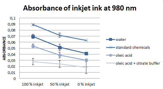
According to literature, the most important wavelengths to evaluate deinking efficiency are 970 and 980 nm, for this reason we concentrated on them. However, the values at these two wavelengths are almost equal, for this reason, only one of them is presented in figure 5.
The significant precondition for accurate results when measuring absorbance is a particle-free solution. However, some paper fibers pass the filter membranes and are present in the flow-through. These residual fibers might lead to inaccurate and unstable values. For this reason, it was tried to dissolve ink by using solvents with different polarity (table 1).
| Solvent | Volume[µL] | relative polarity |
|---|---|---|
| Acetone | 10 | 0.355 |
| Isopropanol | 10 | 0.546 |
| Ethanol | 10 | 0.654 |
Rotary evaporator
After being unable to separate ink from fibers present in flow through, it was decided to try to concentrate ink present there. For this purpose a rotary evaporator was used. The flow through solution was transferred into the apparatus in order to evaporate the water from the mixture. Afterwards, the fibers could be spun down with a centrifuge and the resulting concentrated ink solution could be taken for the absorbance scan. However, the more water was evaporated, the more ink particles strongly fused to the glass vessel’s surface and only the fibers were left. It was tried to dissolve the ink from the walls of the vessel, but we were unable to achieve this.
Grayscale
As the absorbance measurements of the flow-through were not successful, because of the residual particles and the dissolving and concentration of ink failed, scanning of the paper samples was tested. 8-bit grayscale values can vary between 0 (black paper) and 255 (white paper), all values in between describe different shades of gray thus the brightness of the paper. However, brightness alone does not describe paper quality, but it is one of the most important indicators. Both sides of the resulting dry paper disks were scanned in 5 different places on an office scanner. Afterwards, the images were analysed and the grayscale value obtained with the program ImageJ (figure 6).
Flotation-based deinking
In order to improve the deinking mechanism in our laboratory, the experiments were up-scaled. The apparatus and process itself now were much more similar to the ones used in industry (figure 7).
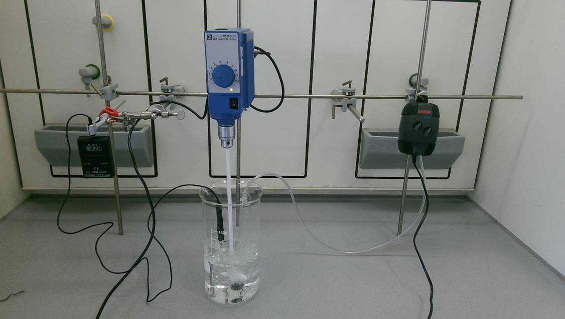
Chemical deinking was carried out using this experimental setup. Chemicals and 50 °C water were added to the beaker together with the pulp. The stirring was constant in order to mix the chemicals and fibers together. After the start of the air pump, foam, collecting ink, starts to form.
After the collection of approximately 1 L of foam, its pH was measured. The result was near 10. Later on, froth was defoamed with acetone so that the absorbance measurements could be carried out. Even though some fibers are always present in foam, it is known that under proper conditions it is possible to reject their loss. However, after defoaming it was observed that froth contains much more fibers than it was expected. Due to the slurry appearance, absorbance could not be measured properly
Ink removal
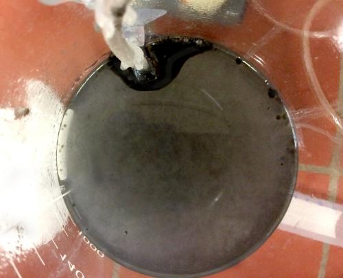
Ca2+ ions are necessary in the deinking process. Previously no chemicals containing Ca2+ were added as they can originate straight from hard water or from paper itself. However, it was decided to add CaCl2 and test its effect on deinking. The experiment resulted in ink being separated completely from fibers as organic phase (figure 8).
Latest deinking system
The newest deinking setup goes back to the small scale filtration-based deinking. The basic principle and used chemicals are the same as mentioned at the beginning. Only few things were changed: A kitchen mixer was used instead of vortexing machine, moreover, pulp after treatment was dried differently as it was decided to use the scanning method as the most reliable way to analyse paper deinking efficiency. For this reason bigger and flatter paper disks were needed. After filtrating the pulp-chemical mixture through the sieve, wet fibers were spread onto the lid of the well plate and were pressed lightly to flatten them. After one day, dry paper disks were scanned with the Li-Cor Odyssey infrared scanner and absorbance values at 700 nm were gained (figure 9). An office scanner was tested as well. However, it was not chosen because it may affect the value by adjusting the light when scanning.
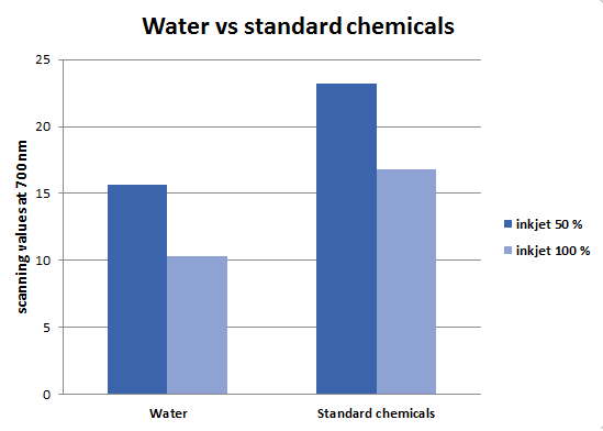
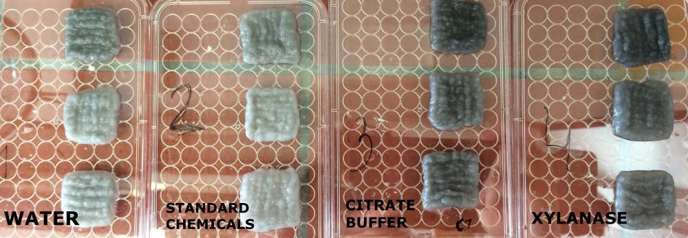
The data from figure 9 proves that the deinking and its analysis system in laboratory scale was established. For this reason, tests of citrate buffer and one of the enzyme, Xylanase, were started. However, all the experiments resulted in visually much darker paper even when compared to simply washed paper pulp (figure 10).
Another problem is citrate buffer‘s crystallization. After the pulp treated with citrate buffer is dry, it tends to show higher values when scanning at 700 nm. This is caused by the crystals of citrate buffer and leads to misinterpreting of results.
Due to the lack of time further experiments could not be carried out. However, the laboratory scale deinking system is established and can give promising results when using enzymes to deink the paper.


