| Line 29: | Line 29: | ||
Based on the integral form of continuity equation for a incompressible fluid, during a given time, the sum of flow volume in each branch is equal to the total volume pumped in the whole chamber. According to Kirchhoff's law, the accumulation of flow speed at the joint point must be zero. It is easy to get the equation that | Based on the integral form of continuity equation for a incompressible fluid, during a given time, the sum of flow volume in each branch is equal to the total volume pumped in the whole chamber. According to Kirchhoff's law, the accumulation of flow speed at the joint point must be zero. It is easy to get the equation that | ||
| − | {{SUSTech_Shenzhen/bmath|equ=<nowiki>L_{AC}*V_1=L_{AB}*V_2+R_{AB}*V_3 \\ | + | {{SUSTech_Shenzhen/bmath|equ=<nowiki>\begin{matrix} L_{AC}*V_1=L_{AB}*V_2+R_{AB}*V_3 \\ |
| − | V_2:V_3=R_{AB}:L_{AB}</nowiki>}} | + | V_2:V_3=R_{AB}:L_{AB} |
| + | \end{matrix}</nowiki>}} | ||
Consequently, we could reach the conclusion that the maximum velocity, average flow rate and the shear force on the bottom of each tunnel is at a ratio of 81:9:1. | Consequently, we could reach the conclusion that the maximum velocity, average flow rate and the shear force on the bottom of each tunnel is at a ratio of 81:9:1. | ||
Revision as of 00:08, 16 October 2016

Model
Microfluidics
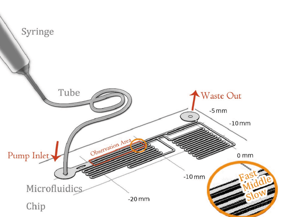
To quantitively measure the response of MS channel on the cell membrane, we designed our experiment manipulated on microfluidic chip. CHO-K1 cells were cultured adherent on the bottom of PDMS tunnel. Stable and flexible force field could be formed surrounding cell, which directly controlled by the pumped-inflow rate. Each time when we applied a constant pumped inflow, cells in 3 different observation tunnel could receive corresponding small, middle, large, 3 level of force magnitude(1: 9: 81). By changing the pumped flow rate, we could measure MS channel response under a series of force.
Mathematical Demonstation
In experiment, when fluid(culture medium F-12K) flowed through the tunnel, the shear force was applied on the wall. Seeing the culture medium as a Newtonian flow, it has a constant viscosity μ,0.012dyn·s/cm2.[1] The shear stress that medium generated on wall is proportional to strain rate. As a result, we could relate the magnitude of stress to the the velocity gradient along the transversal surface of each tunnel. Due to the extremely small scale of microfluidic tunnel (only 0.285mm of width), fluid in it observes the Laminar flow. We could assume there is no turbulence when inflow applied constantly, even at the corners. The modeling of flow between 2 parallel plates applies to such stable state, in which the magnitude of shear stress on the bottom is proportional to the maximum velocity( at the cutline).
Newtonian fluid flows between two wide, parallel plates Flow driven by pressure difference Parabolic velocity profile given by u = V[1-(y/h)^2] where V is the maximum velocity (along channel centerline y=0) Along bottom wall, y=-h, shear stress \tau=\mu \frac{du}{dy}=\mu(-2V\frac{y}{h^2})=\frac{2\mu V}{h} For a constant flow rate within the tunnel, the average velocity remains same \bar V=\frac{Q}{A}=\frac{\int_A udA}{A}=\frac{1}{2}V
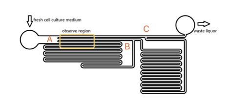
As the shear stress is proved proportional to the flow rate in the tunnel, we designed the chip to achieve that each of 3 tunnels in observation area has the same transversal surface but the gradient (81: 9: 1 from up to bottom) flow rate, also the average speed. The lengths of straight tunnels between AB and AC (LAB, LAC)are 14.3mm and 12.0mm, and the curved tunnels between AB and BC(RAB, RBC) are 108.0 mm and 105.0mm.
Based on the integral form of continuity equation for a incompressible fluid, during a given time, the sum of flow volume in each branch is equal to the total volume pumped in the whole chamber. According to Kirchhoff's law, the accumulation of flow speed at the joint point must be zero. It is easy to get the equation that \begin{matrix} L_{AC}*V_1=L_{AB}*V_2+R_{AB}*V_3 \\ V_2:V_3=R_{AB}:L_{AB} \end{matrix} Consequently, we could reach the conclusion that the maximum velocity, average flow rate and the shear force on the bottom of each tunnel is at a ratio of 81:9:1.
References
- ↑ Booth, R., & Kim, H. (2012). Characterization of a microfluidic in vitro model of the blood-brain barrier (μBBB). Lab on a Chip, 12(10), 1784-1792.


