Difference between revisions of "Team:ZJU-China/Description"
SaltedFish (Talk | contribs) |
SaltedFish (Talk | contribs) |
||
| (25 intermediate revisions by 3 users not shown) | |||
| Line 51: | Line 51: | ||
margin:0px -1% 1px; | margin:0px -1% 1px; | ||
background-color: #e5e5e5; | background-color: #e5e5e5; | ||
| − | padding: | + | padding: 1% 10%; |
} | } | ||
.dcpt4{ | .dcpt4{ | ||
| Line 57: | Line 57: | ||
margin:0px -1% 1px; | margin:0px -1% 1px; | ||
background-color: #fffae6; | background-color: #fffae6; | ||
| − | padding: | + | padding: 1% 10%; |
} | } | ||
.content3{ | .content3{ | ||
| Line 139: | Line 139: | ||
<div class="container"> | <div class="container"> | ||
| − | |||
<div class="dcpt3" style="font-size:20px;line-height:1.5;font-family: 'spr';"> | <div class="dcpt3" style="font-size:20px;line-height:1.5;font-family: 'spr';"> | ||
| − | <div align="left" style="font-family: 'spr';font-size:40px;border-bottom:2px solid #584b4f;"> | + | <div align="left" style="font-family: 'spr';font-size:40px;border-bottom:2px solid #584b4f;">Inspiration from cryptography</div> |
| + | </br> | ||
| + | We are a team full of creative thoughts, and all kinds of interesting ideas generate every day. Since we are particularly interested in cryptography, the idea of combining it with synthetic biology was put forward naturally. | ||
| + | </br> | ||
| + | Taken the limit of manipulating bacteria to realize encryption into consideration, we decided to try an easy mode of encryption in bacteria first. | ||
</br> | </br> | ||
| − | | + | To begin with, some basic concepts of encryption should be clarified. The original information that need to be encrypted is called “the plain text”. The encrypted plain text is called “the cipher text”. A type of document contains the encryption rule is called “the code book”. The system used to realize the encryption of the plain text is called encryption system. Some encryption systems are executed by human, which are rather primitive (like the Caesar Cipher). And some other are executed by machines, which is a leap for computation speed. That is called the cipher machine. |
</br> | </br> | ||
| − | | + | Originally, we adopt a basic encryption system. It uses binary numbers as input and output. After inputting a series of binary numbers (e.g. 1001), cipher machine will encrypt them according to the codebook (e.g. inverting all the even bit), and output the cipher text (e.g. 1100). |
</br></br> | </br></br> | ||
| − | <div align="center"><img src="https://static.igem.org/mediawiki/2016/b/b6/ZJUDES1EX.jpg" width=" | + | <div align="center"><img src="https://static.igem.org/mediawiki/2016/b/b6/ZJUDES1EX.jpg" width="70%"></div> |
</div> | </div> | ||
| − | <div class="dcpt4" style="font-size:20px;line-height:1.5;font-family: 'spr' | + | <div class="dcpt4" style="font-size:20px;line-height:1.5;font-family: 'spr'; "> |
| − | <div align="left" style="font-family: 'spr';font-size:40px;border-bottom:2px solid #584b4f;"> | + | <div align="left" style="font-family: 'spr';font-size:40px;border-bottom:2px solid #584b4f;">Realizing it in E.coli</div> |
</br> | </br> | ||
| − | | + | We intend to build this system in E.coli, and create a biological cipher machine. However, E.coli can’t read or tell binary numbers. The first problem to be solved is how to input and output the information. </br> |
| − | + | What is the “language” that E.coli is most familiar with? The expression of protein! Then we set about to translate the binary numbers into their “language”. </br> | |
| + | In our design, green stands for 0, and red stands for 1. When we use LEDs to light up the bacteria with green light, it means that 0 is input (similar for red light). And the bacteria will use the expression of red or green fluorescent protein to “tell” us the cipher text.</br> | ||
| + | But how to realize this using gene circuit? We build a light control system in E.coli. After being irradiated by corresponding light, protein kinase which is combined with chromophore will phosphorylate the regulatory protein, then downstream promoter will be activated. In that way we realize the input. And there are two ways to realize the change of plain text, which are the expression of fluorescent protein in the same or the other color (green or red). Then another input to decide which way to take is needed. We use arabinose and IPTG to switch between the two ways, combining with the light control system, the AND gate gene circuits are constructed. </br> | ||
| + | We have designed four types of AND gate circuits: | ||
</br> | </br> | ||
(1)Red light controlled promoter + lactose promoter +GFP (output) | (1)Red light controlled promoter + lactose promoter +GFP (output) | ||
| Line 166: | Line 172: | ||
</br> | </br> | ||
| − | <div align="center"><img src="https://static.igem.org/mediawiki/2016/ | + | <div align="center"><img src="https://static.igem.org/mediawiki/2016/a/ac/Zjudesag1.png" width="60%"></div> |
| + | </br> | ||
| + | The process of using this system is consist of three steps: input, encryption and output. | ||
| + | </br></br> | ||
| + | <div align="center"><img src="https://static.igem.org/mediawiki/2016/8/8e/Zjulgni.png" width="50%"></div> | ||
| + | The illustration below shows the whole process of the using of the first mode of biological Enigma.</br></br> | ||
| + | <div align="center"><img src="https://static.igem.org/mediawiki/2016/5/51/Zjudesov1.jpg" width="90%"></div></br> | ||
| + | </div> | ||
| − | |||
| − | |||
| − | |||
| − | |||
| − | |||
| − | |||
| − | |||
| − | |||
| − | |||
| − | |||
| − | |||
| − | |||
| − | |||
| − | |||
| − | |||
| − | |||
| − | |||
<div class="dcpt3" style="font-size:20px;line-height:1.5;font-family: 'spr';"> | <div class="dcpt3" style="font-size:20px;line-height:1.5;font-family: 'spr';"> | ||
| − | <div align="left" style="font-family: 'spr';font-size:40px;border-bottom:2px solid #584b4f;"> | + | <div align="left" style="font-family: 'spr';font-size:40px;border-bottom:2px solid #584b4f;">Greater ambition</div> |
</br> | </br> | ||
| − | Although using this method we could realize | + | Although using this method we could realize the encryption easily, its reliability is not high enough. By calculating the inversion frequency, crackers could speculate the encryption rule, and thus decrypt the cipher easily. A greater ambition is therefore inspired.</br> |
| − | <div align="center"><img src="https://static.igem.org/mediawiki/2016/4/4e/ZJUdes3.jpg" width=" | + | We are inspired by the design of one of the most famous cipher machine, Enigma. Enigma was invented by a German engineer, and used by the German Army during the World War Ⅱ.</br> |
| + | The most amazing part for Enigma is that the codebook changes every time a new letter is inputted. If we are able to change the “codebook” within the bacteria according to time, which is shown in the following figure, then the difficulty of decrypting increase and the cipher machine’s safeness will increased.</br> | ||
| + | |||
| + | <div align="center"><img src="https://static.igem.org/mediawiki/2016/4/4e/ZJUdes3.jpg" width="75%"></div></br> | ||
</div> | </div> | ||
| − | <div class="dcpt4" style="font-size:20px;line-height:1.5;font-family: 'spr' | + | <div class="dcpt4" style="font-size:20px;line-height:1.5;font-family: 'spr';"> |
| − | <div align="left" style="font-family: 'spr';font-size:40px;border-bottom:2px solid #584b4f;"> | + | <div align="left" style="font-family: 'spr';font-size:40px;border-bottom:2px solid #584b4f;">Bigger challenge for gene circuits</div> |
| + | </br> | ||
| + | Obviously, the idea of periodically changing codebook is a bigger challenge for the construction of gene circuits. We consider to realize it by designing a special oscillator gene circuit manipulating two quorum sensing auto inducers (AI-1: AHL & AI-2:DPD) to change periodically, and reach their peak value alternately. | ||
</br> | </br> | ||
| − | |||
| − | |||
| − | |||
| − | |||
</br> | </br> | ||
<div class="row"> | <div class="row"> | ||
<div class="col-md-6"> | <div class="col-md-6"> | ||
<div align="center"> | <div align="center"> | ||
| − | <img src="https://static.igem.org/mediawiki/2016/9/9c/Figure4-1.jpg" width=" | + | <img src="https://static.igem.org/mediawiki/2016/9/9c/Figure4-1.jpg" width="70%"> |
| − | </div> | + | </div></br> |
</div> | </div> | ||
<div class="col-md-6 col-sm-12 expert"> | <div class="col-md-6 col-sm-12 expert"> | ||
| − | <div style="font-size:20px;line-height:1.5;font-family: 'spr' | + | <div style="font-size:20px;line-height:1.5;font-family: 'spr'; vertical-align: middle;"> |
| − | + | When one substance reaches its threshold value, a corresponding gene circuit will be triggered, either to retain the original element, or to change it to the other one, which represents the changing of codebooks. For an example, when a red light is inputted, whether the bacteria will express RFP or GFP is determined by the relative quantity of AHL and DPD. If the quantity of AHL exceeds DPD, the bacteria will produce GFP. | |
| + | Using this method, we could realize the periodic conversion of a code book, which is hard to be deciphered. | ||
| + | |||
</div> | </div> | ||
</div> | </div> | ||
| Line 217: | Line 216: | ||
<div class="row"> | <div class="row"> | ||
<div class="col-md-6 col-sm-12 expert"> | <div class="col-md-6 col-sm-12 expert"> | ||
| − | <div style="font-size:20px;line-height:1.5;font-family: 'spr' | + | <div style="font-size:20px;line-height:1.5;font-family: 'spr'; vertical-align: middle;"> |
</br></br></br> | </br></br></br> | ||
| − | It is hard for oscillation system to maintain stability because of interference from bacteria division, product accumulation and other possible factors. We use micro-fluidic technology to | + | It is hard for oscillation system to maintain stability because of interference from bacteria division, product accumulation and other possible factors. We use micro-fluidic technology to refresh media in time, and maintain the quantity of bacteria. We hope we could observe a more stable, and sturdier oscillation, providing a reliable switch for our cipher machine. |
</div> | </div> | ||
</div> | </div> | ||
| Line 225: | Line 224: | ||
<div align="center"> | <div align="center"> | ||
<img src="https://static.igem.org/mediawiki/2016/a/a7/Figure4-3.jpg" width="90%"> | <img src="https://static.igem.org/mediawiki/2016/a/a7/Figure4-3.jpg" width="90%"> | ||
| − | </div> | + | </br> Danino T, Mondr6agón-Palomino O, Tsimring L, et al. A synchronized quorum of genetic clocks[J]. Nature, 2010, 463(7279): 326-330. |
| + | |||
| + | </div></br> | ||
</div> | </div> | ||
</div> | </div> | ||
| Line 233: | Line 234: | ||
<div class="row"> | <div class="row"> | ||
<div class="col-md-6"> | <div class="col-md-6"> | ||
| − | <div style="font-size:20px;line-height:1.5;font-family: 'spr' | + | <div style="font-size:20px;line-height:1.5;font-family: 'spr';"><img src="https://static.igem.org/mediawiki/2016/9/9b/Figure4-2%EF%BC%881%EF%BC%89.jpg" width="100%" height="100%"></img></div></br> |
</div> | </div> | ||
<div class="col-md-6"> | <div class="col-md-6"> | ||
| − | <div style="font-size:20px;line-height:1.5;font-family: 'spr' | + | <div style="font-size:20px;line-height:1.5;font-family: 'spr';"></br></br></br></br> |
| − | | + | This figure is the actual device we used for our microfluidic experiment. The detailed information is included in <a href="https://2016.igem.org/Team:ZJU-China/Hardware">Hardware page.</a> |
</div> | </div> | ||
</div> | </div> | ||
| Line 245: | Line 246: | ||
| − | <div class=" | + | <div class="dcpt3" style="font-size:20px;line-height:1.5;font-family: 'spr';text-align:left;"> |
<div align="left" style="font-family: 'spr';font-size:40px;border-bottom:2px solid #584b4f;">Overall</div> | <div align="left" style="font-family: 'spr';font-size:40px;border-bottom:2px solid #584b4f;">Overall</div> | ||
</br> | </br> | ||
| − | <div align="center"><img src="https://static.igem.org/mediawiki/2016/ | + | <div align="center"><img src="https://static.igem.org/mediawiki/2016/1/16/Zjudesov2.jpg" width="100%"></div> |
</div> | </div> | ||
| − | <div class=" | + | <div class="dcpt4" style="font-size:20px;line-height:1.5;font-family: 'spr';"> |
<div align="left" style="font-family: 'spr';font-size:40px;border-bottom:2px solid #584b4f;">Part improvement</div> | <div align="left" style="font-family: 'spr';font-size:40px;border-bottom:2px solid #584b4f;">Part improvement</div> | ||
</br> | </br> | ||
| − | For better description of single oscillation system, we measured the response intensity of pluxR to AHL. | + | For better description of single oscillation system, we measured the response intensity of pluxR to AHL. The part we used is <div style="font-weight:bold">BBa_R0062 from ETH_Zurich 2014.</div> |
| − | + | ||
| − | + | ||
<div class="row"> | <div class="row"> | ||
<div class="col-md-6"> | <div class="col-md-6"> | ||
| Line 273: | Line 272: | ||
</div> | </div> | ||
| − | We found that the response threshold of pluxR to AHL isn’t exactly as what shown in ETH_Zurich 2014. | + | We found that the response threshold of pluxR to AHL isn’t exactly as what shown in ETH_Zurich 2014. The minimum response concentration is about 10^-9 M instead of 10^-11M, the maximum response concentration is about 10^-6M instead of 10^-7M. And the relation curve is different with ETH_Zurich 2014, too. We believe that our result are more precise and our model match reality better, since more samples were used in our experiment. |
| − | The minimum response concentration | + | |
| Line 280: | Line 278: | ||
| − | <div class=" | + | <div class="dcpt3" style="font-size:20px;line-height:1.5;font-family: 'spr';"> |
<div align="left" style="font-family: 'spr';font-size:40px;border-bottom:2px solid #584b4f;">Modeling</div> | <div align="left" style="font-family: 'spr';font-size:40px;border-bottom:2px solid #584b4f;">Modeling</div> | ||
</br> | </br> | ||
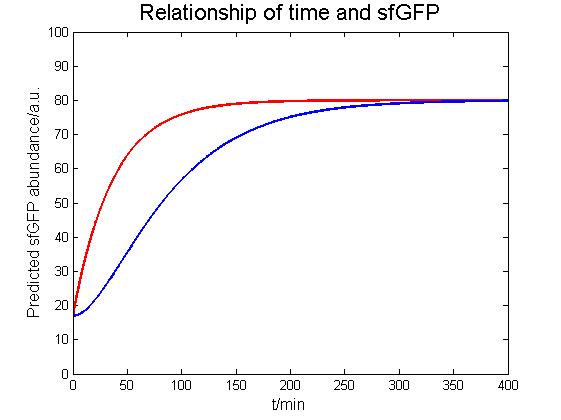
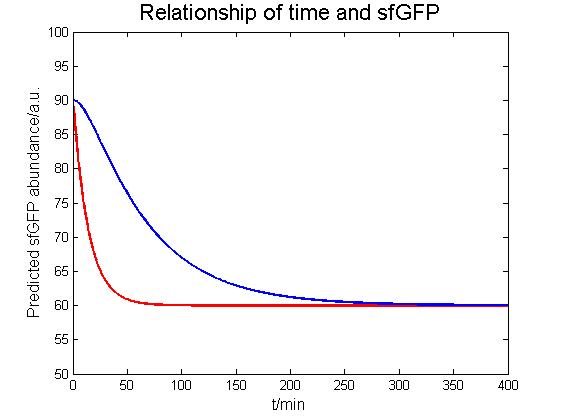
| − | Basing on our experiments, we finally establish three model to support our results of experiments. | + | Basing on our experiments, we finally establish three model to support our results of experiments. In our light-control model, we research the light input model and the AND Gate Model. The light input shows the relationship between the previous light intensity and the output of the Ccas/R system by varying the production rate of sfGFP, p (t), and the sfGFP abundance, g (t). |
| − | In our light-control model, we research the light input model and the AND | + | |
</br> | </br> | ||
| Line 296: | Line 293: | ||
</div> | </div> | ||
<br /> | <br /> | ||
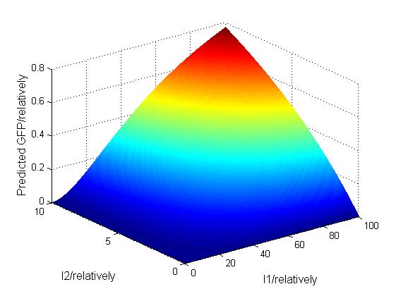
| − | And our logic Gate Model use the mathematical equations to simulate the AND relationship between | + | And our logic Gate Model use the mathematical equations to simulate the AND relationship between the concentration of T7 mRNA, I1, and the concentration of two input substances (In our system, Arbc.), I2. |
| − | <div align="center"><img src="https://static.igem.org/mediawiki/2016/b/bd/Integrated_Model.jpeg" width=" | + | <div align="center"><img src="https://static.igem.org/mediawiki/2016/b/bd/Integrated_Model.jpeg" width="70%"></div> |
</br> | </br> | ||
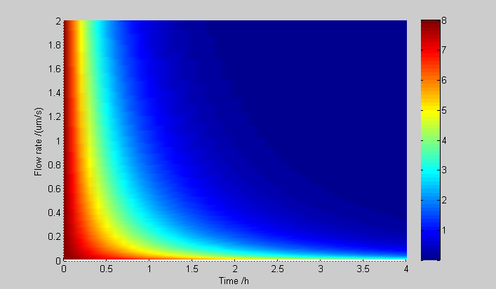
| − | Our infiltration model shows how important role our microfluidic plays in our experiment. We derive a formula to express the influence of the main | + | Our infiltration model shows how important role our microfluidic plays in our experiment. We derive a formula to express the influence of the main channel’s current speed in our oscillation model by analyzing the fluid dynamical process and get an ideal result. |
</br></br> | </br></br> | ||
| − | <div align="center"><img src="https://static.igem.org/mediawiki/2016/6/6a/AHL_Result1.png" width=" | + | <div align="center"><img src="https://static.igem.org/mediawiki/2016/6/6a/AHL_Result1.png" width="70%"></div> |
</br> | </br> | ||
| − | Inflating model provides a foundation for our oscillating model, which is the most important basis of our experiments. With the guidance of our pre experiment, we choose the internal AHL concentration to represent the expression of GFP. Basing on the biological reaction process above, we derived the following set of delay-differential equation model for intracellular concentrations of LuxI (I),AiiA (A), internal AHL (Hi), and external AHL (He). | + | Inflating model provides a foundation for our oscillating model, which is the most important basis of our experiments. With the guidance of our pre experiment, we choose the internal AHL concentration to represent the expression of GFP. Basing on the biological reaction process above, we derived the following set of delay-differential equation model for intracellular concentrations of LuxI (I), AiiA (A), internal AHL (Hi), and external AHL (He). |
<div align="center"><img src="https://static.igem.org/mediawiki/2016/3/3c/Result.png" width="90%"></div> | <div align="center"><img src="https://static.igem.org/mediawiki/2016/3/3c/Result.png" width="90%"></div> | ||
| − | In our models, we finally get | + | In our models, we finally get an oscillation period about 3h which can be controlled by the current speed in microfluidics. In our light-dependent experiment, the optical response time is nearly 3h, which supplies the proof of the interconnection between the oscillation and light-dependent control. |
</div> | </div> | ||
| − | <div class=" | + | <div class="dcpt4" style="font-size:16px;line-height:1.5;font-family: 'spr';"> |
<div align="left" style="font-family: 'spr';font-size:40px;border-bottom:2px solid #584b4f;">Reference</div> | <div align="left" style="font-family: 'spr';font-size:40px;border-bottom:2px solid #584b4f;">Reference</div> | ||
</br> | </br> | ||
| Line 324: | Line 321: | ||
Logic gate: | Logic gate: | ||
</br> | </br> | ||
| − | Anderson J C, Voigt C A, Arkin A P. Environmental signal integration by a modular AND gate[J]. Molecular Systems Biology, 2007, 3(1) | + | Anderson J C, Voigt C A, Arkin A P. Environmental signal integration by a modular AND gate[J]. Molecular Systems Biology, 2007, 3(1): 133.</br> |
</br> | </br> | ||
Oscillation: | Oscillation: | ||
</br> | </br> | ||
| − | 1)Prindle A, Samayoa P, Razinkov I, et al. A sensing array of radically coupled genetic | + | 1)Prindle A, Samayoa P, Razinkov I, et al. A sensing array of radically coupled genetic 'biopixels'.[J]. Nature, 2012, 481(7379):39-44.</br> |
2)Danino T, Mondragón-Palomino O, Tsimring L, et al. A synchronized quorum of genetic clocks[J]. Nature, 2010, 463(7279): 326-330. | 2)Danino T, Mondragón-Palomino O, Tsimring L, et al. A synchronized quorum of genetic clocks[J]. Nature, 2010, 463(7279): 326-330. | ||
</br> | </br> | ||
Latest revision as of 02:49, 7 November 2016


Inspiration from cryptography
We are a team full of creative thoughts, and all kinds of interesting ideas generate every day. Since we are particularly interested in cryptography, the idea of combining it with synthetic biology was put forward naturally.
Taken the limit of manipulating bacteria to realize encryption into consideration, we decided to try an easy mode of encryption in bacteria first.
To begin with, some basic concepts of encryption should be clarified. The original information that need to be encrypted is called “the plain text”. The encrypted plain text is called “the cipher text”. A type of document contains the encryption rule is called “the code book”. The system used to realize the encryption of the plain text is called encryption system. Some encryption systems are executed by human, which are rather primitive (like the Caesar Cipher). And some other are executed by machines, which is a leap for computation speed. That is called the cipher machine.
Originally, we adopt a basic encryption system. It uses binary numbers as input and output. After inputting a series of binary numbers (e.g. 1001), cipher machine will encrypt them according to the codebook (e.g. inverting all the even bit), and output the cipher text (e.g. 1100).

Realizing it in E.coli
We intend to build this system in E.coli, and create a biological cipher machine. However, E.coli can’t read or tell binary numbers. The first problem to be solved is how to input and output the information.
What is the “language” that E.coli is most familiar with? The expression of protein! Then we set about to translate the binary numbers into their “language”.
In our design, green stands for 0, and red stands for 1. When we use LEDs to light up the bacteria with green light, it means that 0 is input (similar for red light). And the bacteria will use the expression of red or green fluorescent protein to “tell” us the cipher text.
But how to realize this using gene circuit? We build a light control system in E.coli. After being irradiated by corresponding light, protein kinase which is combined with chromophore will phosphorylate the regulatory protein, then downstream promoter will be activated. In that way we realize the input. And there are two ways to realize the change of plain text, which are the expression of fluorescent protein in the same or the other color (green or red). Then another input to decide which way to take is needed. We use arabinose and IPTG to switch between the two ways, combining with the light control system, the AND gate gene circuits are constructed.
We have designed four types of AND gate circuits:
(1)Red light controlled promoter + lactose promoter +GFP (output)
(2)Red light controlled promoter + arabinose promoter + RFP (output)
(3)Green light controlled promoter + lactose promoter + RFP (output)
(4)Green light controlled promoter + arabinose promoter + GFP (output)


Greater ambition
Although using this method we could realize the encryption easily, its reliability is not high enough. By calculating the inversion frequency, crackers could speculate the encryption rule, and thus decrypt the cipher easily. A greater ambition is therefore inspired.
We are inspired by the design of one of the most famous cipher machine, Enigma. Enigma was invented by a German engineer, and used by the German Army during the World War Ⅱ.
The most amazing part for Enigma is that the codebook changes every time a new letter is inputted. If we are able to change the “codebook” within the bacteria according to time, which is shown in the following figure, then the difficulty of decrypting increase and the cipher machine’s safeness will increased.

Bigger challenge for gene circuits
Obviously, the idea of periodically changing codebook is a bigger challenge for the construction of gene circuits. We consider to realize it by designing a special oscillator gene circuit manipulating two quorum sensing auto inducers (AI-1: AHL & AI-2:DPD) to change periodically, and reach their peak value alternately.

When one substance reaches its threshold value, a corresponding gene circuit will be triggered, either to retain the original element, or to change it to the other one, which represents the changing of codebooks. For an example, when a red light is inputted, whether the bacteria will express RFP or GFP is determined by the relative quantity of AHL and DPD. If the quantity of AHL exceeds DPD, the bacteria will produce GFP.
Using this method, we could realize the periodic conversion of a code book, which is hard to be deciphered.
It is hard for oscillation system to maintain stability because of interference from bacteria division, product accumulation and other possible factors. We use micro-fluidic technology to refresh media in time, and maintain the quantity of bacteria. We hope we could observe a more stable, and sturdier oscillation, providing a reliable switch for our cipher machine.
 Danino T, Mondr6agón-Palomino O, Tsimring L, et al. A synchronized quorum of genetic clocks[J]. Nature, 2010, 463(7279): 326-330.

This figure is the actual device we used for our microfluidic experiment. The detailed information is included in Hardware page.
Overall

Part improvement
For better description of single oscillation system, we measured the response intensity of pluxR to AHL. The part we used is BBa_R0062 from ETH_Zurich 2014.
 ZJU-CHINA 2016
 ETH_Zurich 2014
Modeling
Basing on our experiments, we finally establish three model to support our results of experiments. In our light-control model, we research the light input model and the AND Gate Model. The light input shows the relationship between the previous light intensity and the output of the Ccas/R system by varying the production rate of sfGFP, p (t), and the sfGFP abundance, g (t).
And our logic Gate Model use the mathematical equations to simulate the AND relationship between the concentration of T7 mRNA, I1, and the concentration of two input substances (In our system, Arbc.), I2.

Reference
Light induced system:
1)Tabor J J, Levskaya A, Voigt C A. Multichromatic Control of Gene Expression in Escherichia coli[J]. Journal of Molecular Biology, 2011, 405(2):315-24.
2)Levskaya A, Chevalier A A, Tabor J J, et al. Engineering Escherichia coli to see light[J]. Nature, 2005, 438(7067):441-2.
3)Olson E J, Hartsough L A, Landry B P, et al. Characterizing bacterial gene circuit dynamics with optically programmed gene expression signals.[J]. Nature Methods, 2014, 11(4):449-455.
Logic gate:
Anderson J C, Voigt C A, Arkin A P. Environmental signal integration by a modular AND gate[J]. Molecular Systems Biology, 2007, 3(1): 133.
Oscillation:
1)Prindle A, Samayoa P, Razinkov I, et al. A sensing array of radically coupled genetic 'biopixels'.[J]. Nature, 2012, 481(7379):39-44.
2)Danino T, Mondragón-Palomino O, Tsimring L, et al. A synchronized quorum of genetic clocks[J]. Nature, 2010, 463(7279): 326-330.
Contact Us
Room 413,Biology lab center, Zijingang Campus
Zhejiang University, YuHangTang Road NO.866
Hangzhou, China
iGEM ZJU-China 2016 Team
igem_zjuchina_2016@outlook.com
igem_zjuchina_2016@outlook.com