Light control
As a cipher machine, it must have the ability to input information conveniently. Therefore, it is crucial to have a rapid and reliable input system. After research and discussion, we finally find the ideal solution: Light-switchable two-component systems (TCSs). These two systems are green-light system (CcaS-CcaR system) and red-light system (Cph8-OmpR system). Besides, our encrypted information is in binary form, this system could satisfy our input requirement. Following is a detailed description.

Oscillation
For better effects, we hope each of the encryption unit could change dynamically, that is, for the same input signal at different times, our system will produce different responses, and this change is a periodic process. We want to use the classic negative feedback loop to achieve it.
 Fig.1
Fig.1
However, this system can only be used in a single bacterium. Among bacteria, due to the differences between individuals, we can hardly observe a group-level stable oscillation. Gene expressions among the whole group need to be synchronized, which needs quorum sensing. Quorum sensing is a system of autoinducers released by bacteria themselves and response correlated to population density to regulate group behaviors like gene expression. Gram-negative bacteria has two kinds of quorum sensing system, and the autoinducers are AHL (Fig.2a) and DPD (Fig.2b).
 Fig.2a
 Fig.2b
 Fig.3a
 Fig.3b
 Fig.3c
 Fig.4a
 Fig.4b
Logic gate
We have achieved information input using light control system, and have decided the transformational rule using oscillation system. The following problem is how to combine these two systems together and we design an AND gate. The main principle we use in the AND gate is using tRNA to identify amber mutation. Protein T7ptag can activate PT7 promoter. When we make two amber mutations on T7ptag, the process of protein translation will be inhibited. After inputting exogenetic tRNA into E.coli, whose feature is to identify amber mutation, these two promoters controlling T7ptag and tRNA have composed the input of AND gate. And the output is the downstream PT7 gene.
 Fig.5
Fig.5
(1)Plamda+PluxR+GFP (2)Plamda+Plsr+RFP (3)PcpcG2+PluxR+RFP (4)PcpcG2+PluxR+GFP
 (1)Plamda+PluxR+GFP
 (2)Plamda+Plsr+RFP
 (3)PcpcG2+PluxR+RFP
 (4)PcpcG2+PluxR+GFP
Basic function
Using light-switchable two-component systems as input, and AND gate circuit to manipulate the input signal, we have already achieved the basic function of the cipher machine.


Advanced function
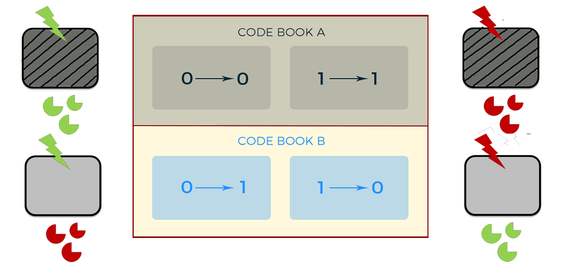
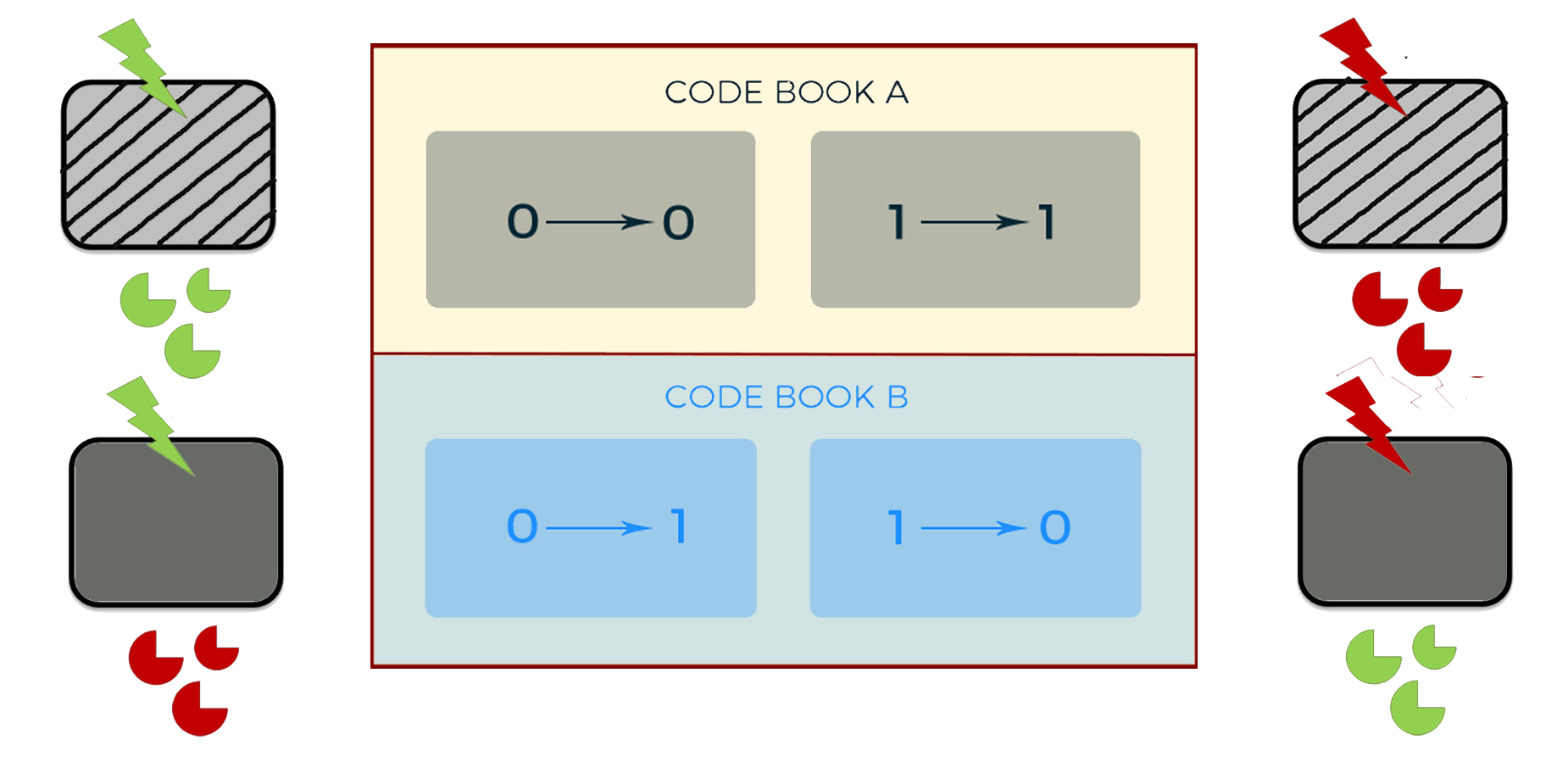
To realize an independent and dynamic encryption, we use logic gates to combine the light control system and the oscillation system. We use AHL to replace Ara, and DPD to replace IPTG. Thus, with the adjustment by the oscillation system, the second generation of cipher machine could change periodically between two different code books all by itself.

Future works
(1)Light control
The effect using red light system to inhibit PopmC is not obvious enough. During the experiment, we integrated the two plasmids mentioned in the original reference into a whole. We suspect that the incoordination happened in the system is due to different copy numbers. In the future, we plan to change the copy numbers and try to find the best effect. Besides, we consider to replace cph8 and RBS before PcyA/ho1.
Also, we want to adopt the blue light control system used by Uppsala_Sweden2011, and compare its influences with red light and green light systems.
In order to describe the light control system more in details, we plan to use multi-mode reading machine to take pictures regularly. Thus we could analyze after how much time being irradiated can bacteria produce the initial response, and draw the response curve according to fluorescence intensity.Currently we use LED lights to irradiate bacteria. The luminance of red LED light is 1200MCD, and 5000MCD for green LED light. In the future, we plan to increase the light intensity, to explore the correlation between light intensity and bacteria’s response time.
(2)Oscillation
In practice, in order to merge several chambers into a whole encryption unit, we have to realize synchronization among chambers instead of within a single one. And this needs strict requirements about the initial bacteria quantity in each chamber and other related factors. So, it has high possibility that desynchronization occurs.
For realizing synchronization as a whole, besides quorum sensing substances, we hope to apply a new micromolecule which could penetrate the PDMS surface, and coordinate bacteria’s gene expression process. After research and discussion, we find that hydrogen peroxide molecule is a good choice. Through redox signalling by hydrogen peroxide (H2O2) and the native redox sensing machineries of E. Coli, we can apply H2O2 to our oscillation system (Fig.11). Using AHL to activate the production of H2O2 in chambers, letting H2O2 to coordinate gene expression in the whole unit, we then realize a perfect synchronization in the whole unit. (Fig.12, Fig.13)
 Fig.11
 Fig.12
 Fig.13
(3)Microfludic
When using hydrogen peroxide as diffusion molecule in oscillation system, we need to modify the microfluidics device. H2O2 can penetrate PDMS material freely. And on a PDMS chip, we need to distinguish different encryption units because each unit has its own oscillation state. So, we have to take measures to block H2O2 from diffusion to different units. We are going to use vertical bonded silicon sheets to achieve this target.
(4)Logic gate
Promoter leak is still existing. In the combination of arabinose promoter and lactose promoter, lactose promoter leak seriously. So we will do the following experiments for further optimization of the system.
1.Change the position of Pbad and Plac, to explore the influences on PT7 caused by T7ptag and tRNA.
2.Replace current promoters with promoters of low leak values, for example, to use salicylate promoter.
3.Add a weaker RBS before T7ptag, for example, J61100.
4.Use computer to simulate the position of T7ptag amber mutation, and find the best mutant site to inhibit the expression of T7ptag completely.
5.Add input and output on plasmids of different copy numbers in order to make our logic gate more precise.
Contact Us
Room 413,Biology lab center, Zijingang Campus
Zhejiang University, YuHangTang Road NO.866
Hangzhou, China
iGEM ZJU-China 2016 Team
igem_zjuchina_2016@outlook.com
igem_zjuchina_2016@outlook.com


